MS3 + MS3X for Mk1 1.8
 03-09-2011, 09:06 PM
#1
Junior Member
Thread Starter

Join Date: Mar 2011
Location: Guildford, UK
Posts: 163
Total Cats: 0
Planning on building this sometime and have trawled through reams of information.
I'll need:
MS330K
MS 23" wiring bundle
MS3x
DB37 for the MS3X
23" wiring bundle for MS3X
Wideband LC1 + G5
IAT Kit w/ally bung
This CABLE
Anything else to add???
If I follow the msextra Guide, what to do in sections 26,27,28. I'll want to run as much as possible from MS3X board, IGN, Inj, Cam, A/C, Idle and Fans.
Step 22, Do I leave out Q16 and jump R43 ?
If I follow Franks' guide,
Step 50, Do I install his Cam/Crank circuit even though I'll use the MS3x Cam ???
Step 65, as per 22 above. Also IGBTIN to JS10 and IGBTOUT to IGN ???
Would I also need to do the PWM converter mod?
Please bear in mind I am nowhere near an electronics expert
P.S. It's a 1995 Eunos V-SpecII
Last edited by Freaky Roadster; 03-10-2011 at 04:02 AM.

Reply
 0
0

0
03-13-2011, 08:34 PM
#2
Junior Member
Thread Starter
Join Date: Mar 2011
Location: Guildford, UK
Posts: 163
Total Cats: 0
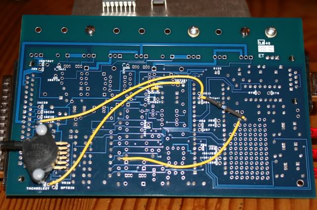
After more reading and help from Braineack, the V3,0 board should look like this with the 4g63 CAS circuit.
Now to sort out the jumpers.
For the 4g63 it's:
TSEL to OPTO OUT
TACHSELECT to XG1
5v from PROTO to top hole of C30
Other Jumps:
s12c to JS9 ? Yes
IAC1A to JS10 ? Yes
5v to JS10 + 470R ? Yes
Pull up Mods ????? Noooooooooooo.
Any help would be much appreciated.
Now to sort out the jumpers.
For the 4g63 it's:
TSEL to OPTO OUT
TACHSELECT to XG1
5v from PROTO to top hole of C30
Other Jumps:
s12c to JS9 ? Yes
IAC1A to JS10 ? Yes
5v to JS10 + 470R ? Yes
Pull up Mods ????? Noooooooooooo.
Any help would be much appreciated.
Last edited by Freaky Roadster; 03-14-2011 at 08:14 PM. Reason: Got some answers.
Reply
0
0
03-14-2011, 05:56 AM
#3
Elite Member
iTrader: (1)

Join Date: Jun 2006
Location: Warrington/Birmingham
Posts: 2,642
Total Cats: 42
Yes, or any circuit you use from the 'IAC' pins won't work
No, that's the cam input for the V3 board, you're getting the MS3x so use the cam input on that instead
Pull up Mods ?????
[/QUOTE]
The pull up mods you are on about are probably ignition out, as above don't bother and use the MS3x instead.
IAC1A to JS10 ?
5v to JS10 + 470R ?
5v to JS10 + 470R ?
Pull up Mods ?????
[/QUOTE]
The pull up mods you are on about are probably ignition out, as above don't bother and use the MS3x instead.
Reply
0
0
03-14-2011, 11:23 AM
#5
Boost Czar


iTrader: (62)
Join Date: May 2005
Location: Chantilly, VA
Posts: 79,493
Total Cats: 4,080
After more reading and help from Braineack, the V3,0 board should look like this with the 4g63 CAS circuit.
Now to sort out the jumpers.
For the 4g63 it's:
TSEL to OPTO OUT
TACHSELECT to XG1
5v from PROTO to top hole of C30
Other Jumps:
s12c to JS9 ?
IAC1A to JS10 ?
5v to JS10 + 470R ?
Pull up Mods ?????
Any help would be much appreciated.
Now to sort out the jumpers.
For the 4g63 it's:
TSEL to OPTO OUT
TACHSELECT to XG1
5v from PROTO to top hole of C30
Other Jumps:
s12c to JS9 ?
IAC1A to JS10 ?
5v to JS10 + 470R ?
Pull up Mods ?????
Any help would be much appreciated.
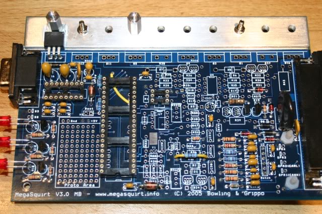
For the 4G63 input circuit follow this:

R12 gets a 470ohm resistor.

and do the mods in RED, GREEN, and PURPLE.
Reply
0
0
03-14-2011, 11:58 AM
#7
2 Props,3 Dildos,& 1 Cat

iTrader: (8)
Join Date: Jun 2005
Location: Fake Virginia
Posts: 19,338
Total Cats: 573
oh whoops... change "NB crank" to "NA CAS". the circuit is different but for sequential I still like the idea of using the main board tsel and js10 for standard inputs and letting the xpander do more fun things.
Reply
0
0
03-14-2011, 08:13 PM
#8
Junior Member
Thread Starter
Join Date: Mar 2011
Location: Guildford, UK
Posts: 163
Total Cats: 0
Cheers guys and thanks again Brain, I wasn't sure of the RED jumps.
Although Richy has a point, I was going to use the CAM input on the 3X.
p.s. edited other post.
Just did a check on 3X Wiring
http://www.msextra.com/doc/ms3/spareports.html#wiring
Part of reply from DIYautotune
"and any of your medium current outputs (24, 6, 25, 26, 27, but I'd save 9 for the IAC valve) may be used for fan or A/C output."
Doesn't mention relay switch or driver but the guide sounds like I'll have to build the circuits, where though?
Last edited by Freaky Roadster; 03-14-2011 at 08:36 PM.
Reply
0
0
 05-21-2011, 07:33 PM
#14
Junior Member
Thread Starter
Join Date: Mar 2011
Location: Guildford, UK
Posts: 163
Total Cats: 0
Glad I checked the resistors, the muppets at Maplin gave me 470K, swapped them for 1/2w 470 5%, so no problems now 
Part way through, and for my first circuit board, I reckon I've got some really neat solders Does help being a goldsmith 
Part way through, and for my first circuit board, I reckon I've got some really neat solders
Does help being a goldsmith
Reply
0
0
 06-08-2011, 08:58 PM
#18
Junior Member
Thread Starter
Join Date: Mar 2011
Location: Guildford, UK
Posts: 163
Total Cats: 0
Am I correct in saying you do not jump 1Q to 1J or 1L to 2S
1Q= A/C Output, goes to pin 29 on the 3X for A/C input to the MS
1J= A/C Input, goes to pin25 on the 3X for A/C output from the MS
2S= A/C Fans, driven by pin 20 on 3X Inj H driver
1L= Fans Cooling, driven by pin 1 on 3X Inj G driver
2K= 5v Ref connect to pin 25 on the MS3
I'll have wideband o2 so 2N=OEM NB is not connected ?
Reply
0
0
 06-18-2011, 05:39 PM
#20
Junior Member
Thread Starter
Join Date: Mar 2011
Location: Guildford, UK
Posts: 163
Total Cats: 0
Sure do, but it's usually gold or silver with a gas/oxy torch.
Smallest pieces of solder I use go down to less than 0.2 Sq MM and approx 0.1mm thick. That's for really lightweight chains, eyes are on the way out so I'm starting to have to use an opti-visor for the real small stuff.
Smallest pieces of solder I use go down to less than 0.2 Sq MM and approx 0.1mm thick. That's for really lightweight chains, eyes are on the way out so I'm starting to have to use an opti-visor for the real small stuff.
Reply
0
0


