MS3 + MS3X for Mk1 1.8
 06-29-2011, 04:23 AM
#21
Junior Member
Thread Starter

Join Date: Mar 2011
Location: Guildford, UK
Posts: 163
Total Cats: 0
Been studying the Madracki.com wiring diagrams (very useful) and it appears 2f and 1k are also sensor grounds.
Is there any reason not to use them as well to spread out the loom a bit?
Is there any reason not to use them as well to spread out the loom a bit?

Reply
 0
0

0
01-27-2012, 02:02 PM
#22

Rather than a new thread, I am going to bump this old thread because I have a couple of questions related to this wiring setup.
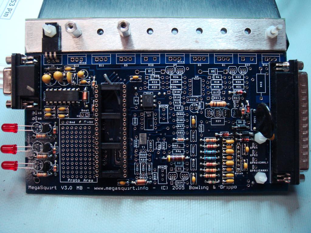
1) I set my board up exactly like Freaky Roadster (MS3 with MS3X for a '94), and my wiring is very similar as well. This shows running the fuel pump off of the MS3 pin 37 (as do all MS guides). However, what circuitry on the board runs the pump? I did not add any transistors, so I'm curious as what exactly is fuel pump related on the MS3 board. For reference:
2) Can you run two injectors off of a single MS3X injector output? This link states, "MS3X fuel - Use the MS3X expansion board's outputs to drive the fuel injectors. Only one injector should be used per output. " I believe the MS3X injector outputs are rated to 5A, so is this adequate to drive two injectors? Eventually I'll go sequential, but I'm just trying to get started with a stock car for now.
Reply
0
0
01-27-2012, 02:24 PM
#23
Boost Pope


iTrader: (8)
Join Date: Sep 2005
Location: Chicago. (The less-murder part.)
Posts: 33,049
Total Cats: 6,608
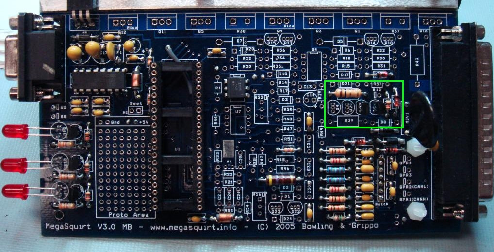
Specifically, Q2 provides a closure to ground to turn the pump on. R16 is between it and the CPU. R40 and Q19 form a protection circuit which limits the maximum current that can flow through Q2, and D4 is a zener diode installed as a flyback diode.
2) Can you run two injectors off of a single MS3X injector output?
Reply
0
0
01-27-2012, 03:05 PM
#26
Senior Member
iTrader: (4)

Join Date: Jan 2008
Location: Falls Church, VA
Posts: 1,361
Total Cats: 17
Wiring:
InjA = pin 19 to 2U (yel)
InjB = pin 16 to 2Y (grn/wht)
InjC = pin 13 to 2Z (grn)
InjD = pin 10 to 2V (yel/blk)
Then under "engine & sequential settings" in TS,
main fuel outputs = MS3X fuel
sequential on = fully sequential
angle specifies = end of squirt
Firing order is A=1, B=3, C=4, D=2
Done.
Whichever route you go, make sure to add ground wires to the MS3X connector- pins 2, 3, 8, 12 and 17. If you don't, your car will probably run like crap. BTDT.
Reply
0
0
01-27-2012, 03:19 PM
#27
Dude, go sequential now. Your 94 already has individual wires for each injector in the stock harness to the ECU. All you have to do is move the two existing wires and then run two new (short) wires to the MS3X and change of couple of settings in TS. You don't have to touch anything under the hood. To leave you no excuse I'll even spoon/force-feed you everything you need to know.
Wiring:
InjA = pin 19 to 2U (yel)
InjB = pin 16 to 2Y (grn/wht)
InjC = pin 13 to 2Z (grn)
InjD = pin 10 to 2V (yel/blk)
Then under "engine & sequential settings" in TS,
main fuel outputs = MS3X fuel
sequential on = fully sequential
angle specifies = end of squirt
Firing order is A=1, B=3, C=4, D=2
Done.
Whichever route you go, make sure to add ground wires to the MS3X connector- pins 2, 3, 8, 12 and 17. If you don't, your car will probably run like crap. BTDT.
-Mike
Reply
0
0
01-27-2012, 03:50 PM
#29
Boost Pope
iTrader: (8)
Join Date: Sep 2005
Location: Chicago. (The less-murder part.)
Posts: 33,049
Total Cats: 6,608
Just as an FYI, it appears that you are using the OPTO input circuit for the crank sensor as per the instructions in post #2.
Don't do that.
Honestly, that circuit is horrible and should die in a fire.
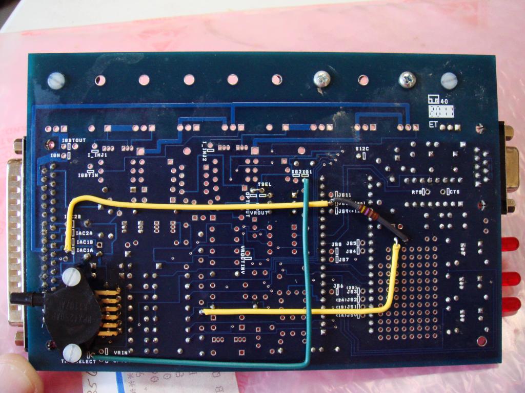
Build (and use) the VR circuit instead. Connect TachSelect to VrIn, and VrOut to Tsel. Adjust R56 so that you get about 2.5 volts at R54. Apply a 1k pullup from Vcc to TachSelect.
Don't do that.
Honestly, that circuit is horrible and should die in a fire.
Build (and use) the VR circuit instead. Connect TachSelect to VrIn, and VrOut to Tsel. Adjust R56 so that you get about 2.5 volts at R54. Apply a 1k pullup from Vcc to TachSelect.
Reply
0
0
01-27-2012, 06:15 PM
#30
Junior Member
Thread Starter
Join Date: Mar 2011
Location: Guildford, UK
Posts: 163
Total Cats: 0
Ok, embarrassment time, still not had the time to install it.
So the VR is superior than the 4g63 set up, what do I need to unplug before installing the VR mods on the V3 board? Help needed please Joe due to being in a hazy alcoholic induced stupor.
So the VR is superior than the 4g63 set up, what do I need to unplug before installing the VR mods on the V3 board? Help needed please Joe due to being in a hazy alcoholic induced stupor.
Reply
0
0
 02-19-2012, 07:40 PM
#33
Junior Member
Thread Starter
Join Date: Mar 2011
Location: Guildford, UK
Posts: 163
Total Cats: 0
Cheers guys, added the VR + Pull Up circuit but left in the 4g63 components as it's a pain getting stuff out safely.
Pulled Tachselect to XG1
Pulled TSEL to OPTOUT
Pulled 5v to top of C30
Do I pull IAC1A to JS10 and 5v to JS10 through 470 Ohm resistor or leave them in?
Do I change any settings in TunerStudio? Currently set to 4g63
Pulled Tachselect to XG1
Pulled TSEL to OPTOUT
Pulled 5v to top of C30
Do I pull IAC1A to JS10 and 5v to JS10 through 470 Ohm resistor or leave them in?
Do I change any settings in TunerStudio? Currently set to 4g63
Last edited by Freaky Roadster; 02-19-2012 at 08:59 PM.
Reply
0
0
02-21-2012, 03:22 PM
#35
Senior Member

Join Date: Nov 2007
Location: Belgium
Posts: 999
Total Cats: 73
You are correct sir. When I come across a picture that's more clear or more tidy than what I have, I usually steal it  .
.
In the case of a 90-97, I need to steal it all as I haven't actually built one. I just gather the info for my build how-to's, hoping someone can benefit from them. FWIW, I used one of Stucky's pics as well .
.
.In the case of a 90-97, I need to steal it all as I haven't actually built one. I just gather the info for my build how-to's, hoping someone can benefit from them. FWIW, I used one of Stucky's pics as well
.
Reply
0
0
02-21-2012, 06:11 PM
#36
Junior Member
Thread Starter
Join Date: Mar 2011
Location: Guildford, UK
Posts: 163
Total Cats: 0
No problem Frank, some people get a bit nasty when using pictures without consent but I'm glad it was of use for you.
For my last questions in post #33, no mention of using the jumpers and pull up from 5v to JS10 to IAC1A on your build, so I reckon I'll disconnect that.
No idea though, if I need to change Tunerstudio settings from 4g63 to ??? or leave it.
For my last questions in post #33, no mention of using the jumpers and pull up from 5v to JS10 to IAC1A on your build, so I reckon I'll disconnect that.
No idea though, if I need to change Tunerstudio settings from 4g63 to ??? or leave it.
Reply
0
0
02-21-2012, 06:49 PM
#37
Senior Member
Join Date: Nov 2007
Location: Belgium
Posts: 999
Total Cats: 73
If you use the MS3X VR circuit + pullup for your cam in, then you don't need JS10 on the mainboard, so you can remove that stuff. The type of input circuit has no effect on the wheel decoder so leave it at 4G63.
Reply
0
0
02-21-2012, 07:50 PM
#38
Junior Member
Thread Starter
Join Date: Mar 2011
Location: Guildford, UK
Posts: 163
Total Cats: 0
Thank you very much 
After looking at the way you have the loom connector built into the box, I was wondering if it's also possible to lay out the MS3 and 3X side by side to the V3 board. Possibly using jumper wires to a break out board for the 40 pin connections. Or maybe some type of ribbon cable.
I remember some people having problems in where to put the MS3 due to the extra thickness of the box.
Reply
0
0
02-22-2012, 11:54 AM
#39
Senior Member
Join Date: Nov 2007
Location: Belgium
Posts: 999
Total Cats: 73
You could build a cable like this http://ist.uwaterloo.ca/~schepers/1541par.html
Or you can get creative and move the map sensor away from the underside and lower the mainboard one or 2 steps, creating more room on top for the MS3 board.
Then try to lower the MS3 cpu as much as possible by either removing one of extra 40 pin dips or using a 40pin dip with very long pins so you can adjust the height.
It'll be a close fit, but you might be able to squeeze the MS3 board in a normal height case that way. The usb connector is a big wart though.
And of course you'd still have to find a solution for the X.
Last edited by WestfieldMX5; 02-22-2012 at 12:04 PM.
Reply
0
0
02-22-2012, 06:37 PM
#40
Junior Member
Thread Starter
Join Date: Mar 2011
Location: Guildford, UK
Posts: 163
Total Cats: 0
That's the sort of idea I had, nice find.
I think the boards would go side by side, V3 to the right and MS3 and 3X to the left. Each side being one half of the MS3 box. Then figure out best place for the 64 pin connector.
That's just a little idea to mull over.
I think the boards would go side by side, V3 to the right and MS3 and 3X to the left. Each side being one half of the MS3 box. Then figure out best place for the 64 pin connector.
That's just a little idea to mull over.
Reply
0
0


