
90 FE-dohc (FE3) Turbo

Thread Starter
Elite Member
iTrader: (5)
Joined: Jan 2005
Posts: 7,486
Total Cats: 372
From: Atlanta
CR Auto Collision in Snellville. Chico is the owner and he's got a pretty understanding of how to paint a car based on what it's worth, or what the owner wants. I explained to him that I had about $800 in the car as it rolled up and that I wanted a color change. He did the color change for $800 and some extra body work $100. That included the hard top which I have some issues (small bubbles at the base) BUT that should be covered under the "any issues at all" one year warranty.
Brainy- they're price because you want a good one. One option is to buy used- I've had some very good used buys from BH.
Brainy- they're price because you want a good one.
One option is to buy used- I've had some very good used buys from BH.
Reply
 0
0

0


Thread Starter
Elite Member
iTrader: (5)
Joined: Jan 2005
Posts: 7,486
Total Cats: 372
From: Atlanta
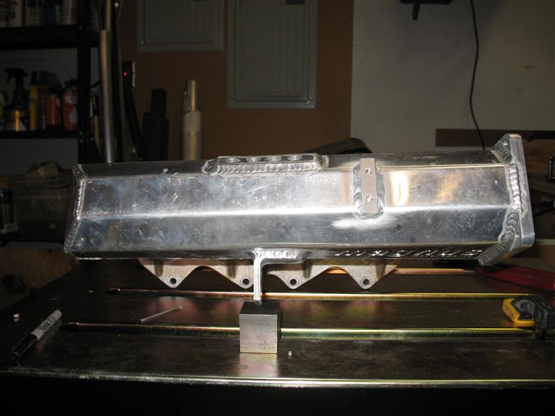
It was just a matter of the right person wanting some spare parts I had and the deal was struck to make my hybrid intake manifold a reality. Local tuner/fab guy and forum member Ferdi pulled off a phenomenal execution.
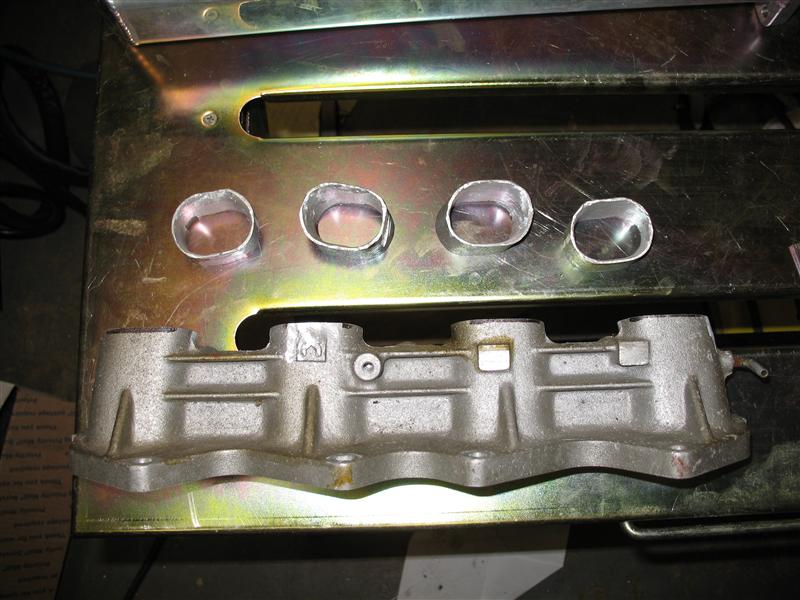
Magnus manifold and FE flange as handed to Ferdi:

More trim on both parts for improved port/runner alignment:
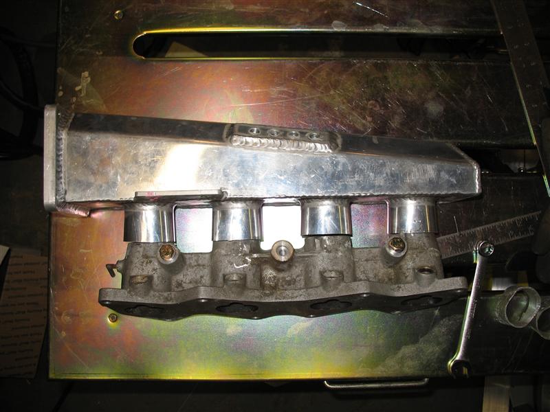
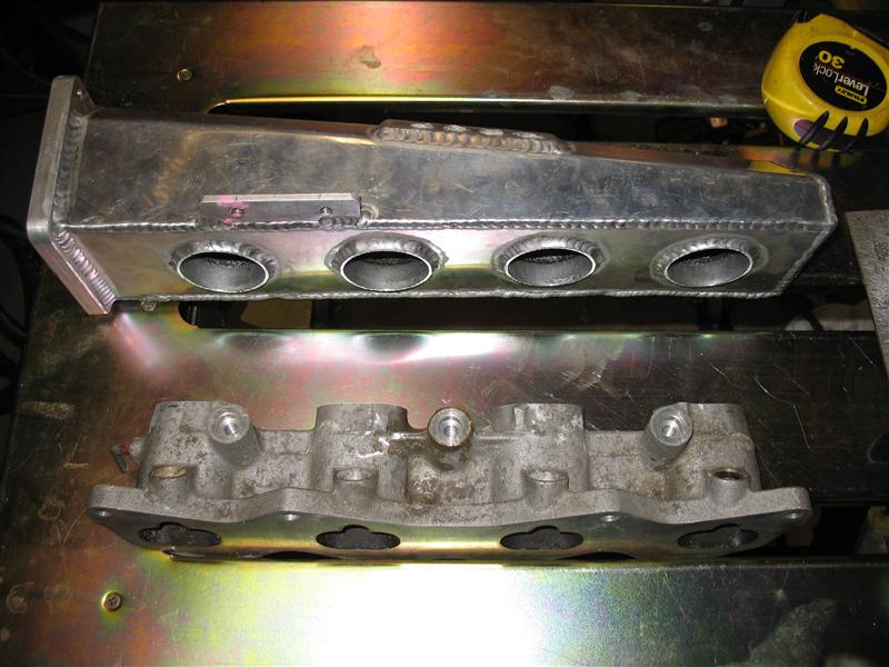
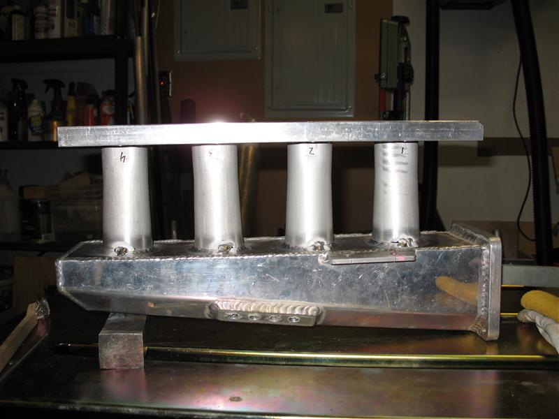
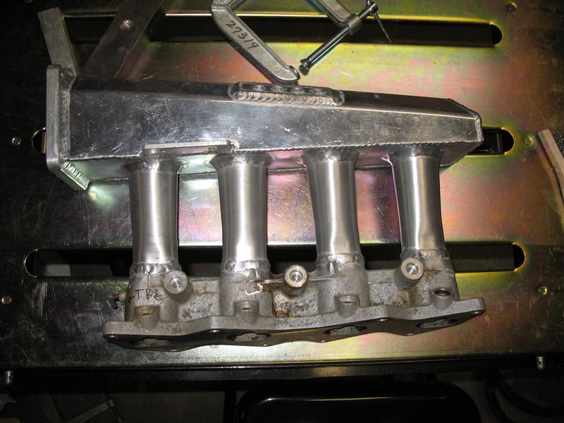
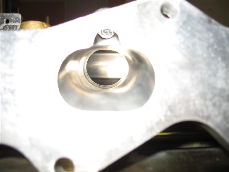
Finished manifold, ported, support arm tab and throttle cable bracket boss added.
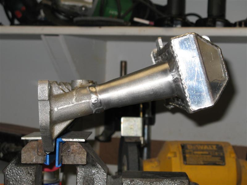
Magnus manifold and FE flange as handed to Ferdi:
More trim on both parts for improved port/runner alignment:
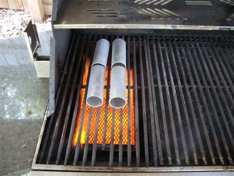
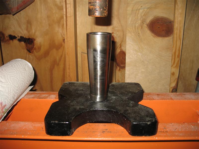
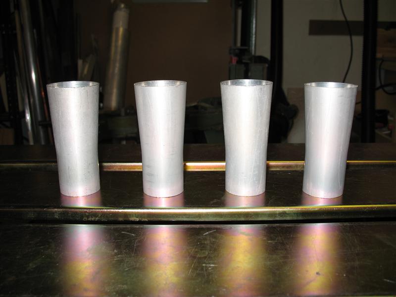
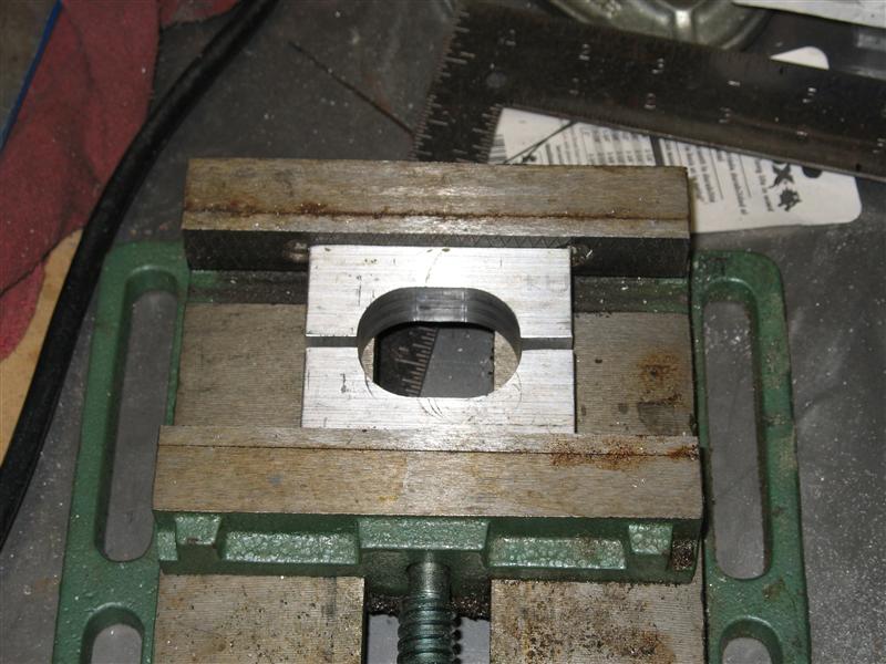
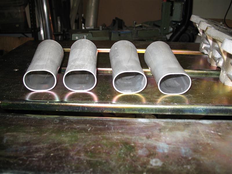
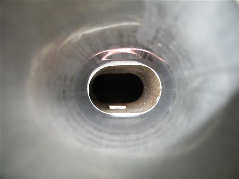
This is where it gets interesting. The original Magnus runners were 2"OD tubing, but the best match to the stock ports was ~1.65"OD tubing. I needed to make some nice transition funnels and the last thing I wanted to do was slice a tube lengthwise and form them myself. So, I lathed a steel bar into a tapered mandrel, annealed the tubes, went to the hydraulic press, and to my surprise everything worked like it was supposed to, which is seldom the case... Pressing out the mandrel after pressing it into the tube was exciting - it almost maxes out the 20-ton press and once it finally lets go you better have something underneath to catch it, it's pretty much a small explosion, lol. By the way, to anneal aluminum you just scribble some sharpie lines on the tubing, heat it up until the marks disappear, and then let it slowly cool down. The thermometer on my grill hood maxes out at 700�F and that's about the time the marks burned off. I am sure the temperature at the grates is much higher.
Finished manifold, ported, support arm tab and throttle cable bracket boss added.
Reply
0
0


Thread Starter
Elite Member
iTrader: (5)
Joined: Jan 2005
Posts: 7,486
Total Cats: 372
From: Atlanta
Good question. Work dominates me atm. But the garage is complete. I'm wiring the lift this weekend. I need a plan to do the swap. At this point I'm thinking I should put the crusher on the lift and start parting it. Once that's done and cleared out, I'll have the full space available of that car to start the swap into the new car.

Reply
0
0

Thanks for the writeup on the intake manifold... that gives me an idea of some new things that i thought that i wouldnt be able to do with my tooling that i had. or more importantly didnt want to bother doing.
Reply
0
0


Joined: Jun 2005
Posts: 19,338
Total Cats: 574
From: Fake Virginia
Reply
0
0

Reply
0
0


