When you click on links to various merchants on this site and make a purchase, this can result in this site earning a commission. Affiliate programs and affiliations include, but are not limited to, the eBay Partner Network.
I finished grad school in December, so naturally my reward to myself is another long term project . I've wanted a car project for as long as I can remember, but my learning addiction has made it difficult to do much more than maintenance and bolt-ons. I decided on a LFX-swapped Miata because it's a decent project fab-wise, reasonably priced for the performance, and documented well enough that I won't be entirely breaking new ground. Enter my chassis: a 102k-mile 2002 SE in Blazing Yellow. It came with a thick stack of service records that almost makes me feel bad about modifying it.
Behind: the reason I can afford this project, my 312k-mile 98 Integra that (I won't let) die
My goal is to build a car that's comfortable enough for a 4-hour road trip and is also capable for the occasional track day. I'd like to drive it on a regular basis, and I know if it's super uncomfortable I'll only drive it a few times a year (been there, done that. It's too hot in NC to not have AC). Drivetrain-wise this means AC, power steering, an exhaust system that doesn't make my ears bleed, and soft-ish engine mounts.
Now that I've got a chassis I need to:
1. Pull and sell the engine, transmission, diff, and whatever odds and ends people will buy
2. Source and buy an engine, transmission, and diff
3. Buy a welder
4. Buy the V8R kit, harness, ECM,…
Step 1 is cash positive, whereas the remaining steps require a lot of investment up front. I'm hoping that selling the existing drivetrain will cover most of the cost of the LFX, but I'll need to save for the welder and V8R kit. While I'm saving, I've taken the opposite path of most other builds and started on the wiring first. I'll make a separate post on that soon. Anyways, I'm planning on documenting the build process here for others (as well as myself for when I forget details in a month) and I wanted to introduce myself!
I'll try to post my references when they're useful, below is a list of build threads that were super helpful in researching the process:
Sweet, another build thread I can crib from! Awesome job putting all the build links on that post btw. I've been thinking about starting a general "Official LFX swap silly question thread" for general advice. I've finally started working on my LFX project again. I'm a terrible procrastinator and that coupled with the feelings like I'm a little over my head on this thing it kills my motivation at times. It's funny that I bought a Blazing Yellow car at one point to put the engine in after I had a big 'off' on a mountain run in my 10AE. My wife decided she didn't like the yellow so I switched to white '02 after seeing it for a killer deal on CL. I made a small profit on the yellow car so it worked out okay. Anyway I'm looking forward to seeing your progress on the project!
Looking forward to reading more! I think you will be very happy with your car when your done. They are a blast to drive. Holler if I can be of any help.
Small world, I think we're about 2 hours apart. Might come in handy at some point
Originally Posted by rdb138
Looking forward to reading more! I think you will be very happy with your car when your done. They are a blast to drive. Holler if I can be of any help.
Thanks for the offer! I'll definitely keep that in mind
Since I've got some time before I spend a bunch on hardware and tools I figured I'd go ahead and get started on the wiring. It's mostly information gathering and planning so it makes sense to do it now. At a high level we need to interface the stock LFX harness:
With the Miata chassis harnesses:
Going into this I thought the Mazda engine harness would be like every Honda I've worked on, in that the engine harness would disconnect from the chassis at a few points and the whole engine + harness would come out. It would be easy, then, to leave the chassis-side harnessing in place in case I needed anything in the future and simply add the stand-alone LFX wiring.
Mazda decided to take a different route and build the engine harness into the chassis, which makes our integration significantly more complicated. Your choices are either cut, insulate, and pretend the unnecessary engine wires don’t exist, or depin and remove them entirely from the engine harness. Because of the classic "I'm in there anyways" argument I'm planning on removing \ depinning the unnecessary wires from the engine harness (up to the point that I don't have to take the entire chassis harness apart).
Fortunately the LFX harness is pretty self-contained in terms of running the engine, although there will be a few points that the two harnesses need to touch. My objective is to keep the two systems as separate as possible to minimize work and maximize documentation re-use - I'm ok with a few additional pounds of unnecessary wiring to save myself tens of hours of work, not to mention debug time if I get it wrong.
To run the engine, the chassis needs to provide the engine harness with:
Always-on battery voltage
Switched battery voltage
The engine harness needs to provide the chassis (separate from the chassis harness) with:
CAN bus (to gage cluster & OBD2 port)
Throttle pedal wiring
Power to the fuel pump relay (enables re-use of Miata fuel pump wiring)
Because we're not using the Camaro fuse box (which is truly enormous, google it), we'll need to add a new fuse and relay box that controls:
AC compressor
Fans
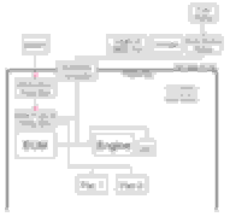
At a very high level, this is how I'm planning on interfacing the two systems:
Detailed planning starts with good schematics for both the Miata and Camaro. Miata chassis wiring changed every 2 years for the NB, so it's important to start with the correct wiring diagram for your car. The Mazda ones are way better:
The Camaro manual is huge (~100Mb) so I'll share it from my google drive. I wish there was a more reliable place to keep it, though - if you feel like hosting it don't hesitate to reach out. EDIT: this site has service manuals for almost every car up to 2013
The next step, now that I've got a more clear idea of what I'll be doing and I have the appropriate schematics, is to pull the Miata engine and start stripping back the harness. I'll make another post detailing that process, which will likely take way longer than the LFX-side. In parallel I'll start designing the LFX harness modifications.
Exciting choice! LFX swap on a Miata sounds like a fulfilling project. Enjoy the journey and modifications! Hello, casino lover Wanna add an extra layer of excitement to your gaming? The best Canadian PayPal online casino are here you can check by clicking on this https://casinosanalyzer.ca/online-casinos/paypal site. Let's turn bets into bucks and create some unforgettable winning moments! I am also using this website to find online real money gaming sites and earned a lot of money by winning games on those sites which I found with the help of this incredible platform.
Last edited by CarlSnoddy; 08-21-2023 at 08:22 AM.
Had a productive weekend and removed the drivetrain despite the 101�F heat index (!). I put the chassis on wheel dollies and tucked it away in front of the other two cars. It's not exactly easy to get to, but it's easier than it being outside.
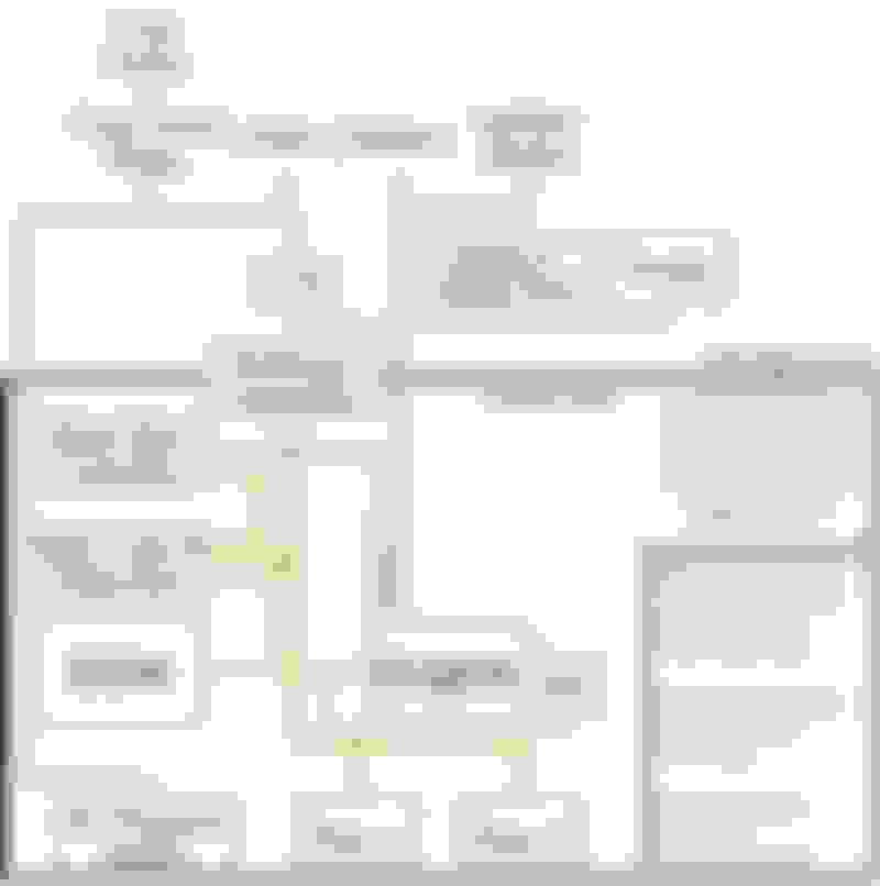
In parallel I've been working on the wiring - I'm starting with a high level block diagram, now on revision 3:
There are three functions where the Miata and new harnesses interface:
Fuel pump
AC compressor
Fans
Fortunately there is an emissions connector in the Miata harness, x-16, where the AC "command compressor on" signal and fuel pump relay coil are present. Ideally I'll be able to connect my interior harness to this connector and avoid splicing into the Miata harness. Obviously I'll be modifying it pretty significantly anyways, but it should draw a clean line between the two systems.
The Miata PCM grounds the fuel pump relay to enable it, and the other side of the coil is connected to switched power through the main relay. The e39 uses a return-less system and controls the fuel pump speed via a PWM signal to the fuel pump control module. I should be able to re-use the stock Miata fuel pump relay by connecting the non-x-16 side of the relay coil to ground and connecting the e39 fuel pump PWM signal to x-16. @rdb138 used this approach and it's worked fine for him - I'll probably add a flyback diode across the relay in case the e39 output isn't protected.
For the AC compressor, I'll probably take the same approach@gooflophaze did and wire up a "dumb" AC compressor control circuit. I looked into using the e39 output, which would be nice since it compensates for the added load and turns the fans on, but it would require the HVAC control module or knowing what message to send the e39. Since I don't have a Camaro, I'll take the "dumb" approach for now. If anyone knows what message to send the e39 to turn the AC compressor on, I'm all ears
The fans are probably the easiest since the e39 has relay control outputs. Those will get wired in a low\high speed configuration similar to the Camaro.
Alternator control is another question I need to address - the e39 controls the field coil (and therefore how much voltage the alternator produces). The ECM determines how much voltage the alternator should produce based on a "battery current sensor" in the "battery housing" (according to the Camaro schematics), which I obviously won't have. I believe @gooflophazeis working on a control module, but I don't think it's ready yet. Others have replaced the factory alternator with a simpler alternator, but according to gooflophaze if you just disconnect the alternator connector (not the wire) it should fall back to 13.8V. It's not perfect, but it's probably good enough.
I think I've accounted for all of the signals, so now it's on to making schematics for each of the new harnesses and picking out connectors. I'm a little worried about putting the throttle pedal through a connector since @ThePass (and @rdb138 , I think) had issues with any sort of noise putting the ECM into "safe" mode. I'll start out with a good, aerospace-grade connector and if I run into issues, I'll bypass the connector and run straight from the ECM to the throttle pedal.
I've seen others (@griff ?) connect a flex fuel sensor into the e39 but I'm not sure where it gets connected - I'm guessing through the AC pressure sensor input?
I think I've accounted for all of the signals, so now it's on to making schematics for each of the new harnesses and picking out connectors. I'm a little worried about putting the throttle pedal through a connector since @ThePass (and @rdb138 , I think) had issues with any sort of noise putting the ECM into "safe" mode. I'll start out with a good, aerospace-grade connector and if I run into issues, I'll bypass the connector and run straight from the ECM to the throttle pedal.
FYI...I didn't have any issues with the throttle pedal, it was @LukeG who did. He made a few different changes, but in the end believed it was the High Pressure Fuel Pump that was having issues, not the throttle pedal wiring (although he redid the wiring for the throttle a couple of times if memory serves). I guess Andrew Keisler has had the issue enough with his kits, that he just always swaps the High Pressure Fuel Pump as insurance.
Also alternator wise, mine charges at 13.4 volts, 13.8v seems a bit optimistic from my observations, it will sometimes charge in the 14v range for a minute or so after start up, but 13.4v seems to be the average. Obviously a bit low, but never had any issues. I'm also running a LiFePo4 battery. They don't like to be overcharged / car starts every time, so I decided to not mess with it.
I've been continuing to disassemble the car - first by removing the seats and dash, then the differential and axles
The interior was straightforward but the axles were stuck in the hubs. PB blaster, a 4lb sledge, and a wooden block didn't budge either side - I knew the wood would absorb a lot of the impact but it was all I had on hand at the time. I bought an air hammer and after probably 20 minutes on one side, still nothing. A friend of mine is a mechanic, he suggested I rest a ball peen hammer on the axle and hit that with the sledge, using the axle nut to center the ball peen. (double-hammer trick). That got the driver's side out in about 5 minutes.
The passenger's side was still being stubborn, however. After about 40 minutes with no success I broke out the torch, heating the hub for a few minutes followed by more sledge-ing and air hammering. 20 more minutes of that and the axle finally started to move, but by now the axle had mushroomed enough that the nut was stuck on. Fortunately I was able to spin the nut with a breaker bar enough to clear whatever threads were left and remove it, then air hammer the axle the rest of the way out. The axle was pretty banged up, and I need a new hub and wheel bearing, but at least I can reuse the knuckle.
With the entire drivetrain removed I've been focusing on selling what I can to free up space - I don't think I could fit the new engine in my garage at the moment. In the meantime I've been working on the wiring. I'll make a post when I'm done, that way the information is all in one spot. I ended up stripping the factory harness of the unused wires, but at least I had help.
Looking good! Have you sourced an engine and trans, yet?
Glad you posted your fun with the hubs and axles. Ive been considering building the subframe from scratch, I know I�m going to have issues getting the hubs off, and I�m going to need new ones anyway, figured I�d avoid fighting with them and just build them fresh with new (or refreshed) parts.
I haven't sourced the new drivetrain yet, that's on my short list. I need to figure out if it makes sense to buy an auto engine and trans separately or to find a full drop-out from a Camaro. Keisler recommends the auto route since the engines are cheaper and lower milage, but that means I'd need to source the engine accessories and wiring harness separately. Not only is that a pain to source everything, but I'm guessing it could end up being more expensive after you buy all the missing one-offs.
I know a guy who built his own subframe, I can put you guys in touch if you're interested. Regarding the hubs, it was definitely not all that fun, but I think it was made worse because I suspect the RR brake caliper got stuck at one point and cooked the axle in there. That corner has a new brake caliper, the LR does not and was easier (a relative term) to remove. Double hammer method is definitely the way to go, though.
I'm ok with a few additional pounds of unnecessary wiring to save myself tens of hours of work, not to mention debug time if I get it wrong.
Welp, that didn't last long� I'll include details of what all I removed in my (large and growing) wiring post.
I think I've removed just about everything I can from the car - now I can finally start building new things. I'd like to wait until Thanksgiving to order a mount kit (V8R usually has a sale on Thanksgiving day) and I'm taking a TIG course through my local community college starting in Jan, so I'll probably hold off on the welding until then. That leaves wiring and fuel, so I've been focusing on those.
I got lucky with the fuel system - a friend of mine had a spare V8R kit he sold me for $50 (sans fuel pump and a few fittings). Considering the push-on to AN fuel fittings and c5 fuel filter \ pressure regulator are $17 apiece \ $39 and V8R's kit is somehow almost $500 I couldn�t pass it up. I'm going to order a DW200 with Miata install kit and figure out the rest as I go. @gooflophaze and @rdb138 both said in their build threads that they'd run the fuel lines down the driver's side if they had to do it again, so that's what I'm planning on doing.
I did some digging on the evap system, and I think I got lucky with an 00+ car. @rdb had a ton of hoses to deal with for the tank vent, but it looks like that's confined to the 99 model year - the 00 and 02 have much different layouts. I'd prefer the car not to smell like gas so I'm going to leave the stock charcoal canister \ air filter \ evaporative chamber system in place and just block off the (1/4") port that would normally go to the engine. From what I can tell, the evap system normally vents to atmosphere through the charcoal canister when the canister drain cut valve (CDCV) is unpowered, so simply leaving it unpowered should allow the tank to "breathe" as if the car was off. I tested this by taking the charcoal canister out and making sure there was flow in both directions (in and out of the tank) through both the charcoal canister and CDCV \ air filter \ evap chamber. Seems simple enough, what could go wrong?
I've spent more time planning the wiring than I care to admit, but I think the results were worth it. I've broken this post down into two sections, removal of the old stuff and design of the new stuff. Wiring supplies cost ~$550 after tax and shipping, so buying a pre-made harness for $1200 is a deal! I chose to roll my own since the pre-made harness doesn't include control for the fuel pump, fans, or AC compressor, plus I'll feel more comfortable having a schematic and better understanding of how it all fits together.
Removing the old stuff: factory wiring
Removing the factory wiring was easier than I was anticipating, just time consuming. Engine and chassis harnesses are mostly separate and interface at two connectors, x-16 and x-24 (in my 02, other years may be different). X-24 has fuel tank signals on it (tank level, pressure, etc.) and x-16 has everything else. I thought the engine harness in earlier years were bundled with the chassis harness, but at least for my car I was wrong.
I started removing the unnecessary stuff from the chassis harness by first labeling all the things I didn't need (cruise control, immobilizer, fuel pump, fan, and AC compressor relays, clutch interlock switch, diagnostic port, etc.) and depinning those connectors. I traced those wires back to where they terminated on the other end - either a crimped butt connection in the harness or another connector - and removed the wire there. It was a ton of unwrapping 20 year old electrical tape, so some disposable gloves came in handy. A right-angle pick was also helpful to tear electrical tape without damaging wires in the event I couldn't find the end to unwrap it. After all was said and done I was left with approximately 3 gallons of used electrical tape:
Air bags
My intention going into this was to keep the airbags since this is a street car. The more I thought about it, though, I really wanted an aftermarket steering wheel, which would disable the air bag system anyways unless I faked it out with a resistor. Who knows what the system would do in a crash with a resistor installed - it may or may not work. I concluded that it made sense to remove the whole system, which I wasn’t super excited about, but it makes logical sense. Most of this was pretty simple, the controller sub-harness connects to the chassis through connector S1-05. There were wires directly from the controller to the drivers and passenger air bags, but those were easy enough to remove since everything was apart.
A very important piece of information I learned after the fact - apparently the factory NB seatbelts have a collapsible member which allows more body motion in a crash, and is designed to work in conjunction with the airbags. More body motion without airbags seems like a bad idea, so I'll be replacing them with NA seatbelts and cutting the loop in the drivers-side belt. This is apparently the configuration that non-SRS NA's got. Feels like a step backwards safety-wise, but that aftermarket steering wheel tho.
I ended up removing about 10 lb of factory wiring, including engine harness:
And the engine bay after factory wiring removal and re-wrapping with tessa tape:
I'll write this assuming you've already read gooflophzes LFX harness and electrical tools posts. As I mentioned in my first post, my objective was to make the LFX stuff as standalone as possible and have a few, clearly defined and easily separatable interfaces with the chassis harnessing. After sifting through both the LFX and Miata wiring diagrams I created the attached schematic. If (probably when) this gets revised I'll keep this post up to date.
I then had to pick out individual components, which was probably harder than the schematic since there are many details and I was designing and sourcing at the same time. The outcome is the attached BOM, which includes just about everything you'd need to build this from scratch. I compared prices from all 4 suppliers, so the price reflected is as close to the minimum as I could get. The BOM and schematic tell you the "what", and I've included the "why" for my design decisions below.
Powertrain relay
I used the same powertrain relay as gooflophaze since I've been told the factory main relay is a weak point. It provides fused power, both switched (controlled by the factory main relay) and unswitched to the LFX harness, fans, and fuel pump. It's also a convenient point to disconnect power via the ring terminals.
Inertia switch
I've seen others use inertia switches on their fuel pump relay and it seems like cheap insurance in the event of a crash, so I included one on my build as well. Since the fuel pump is switched through the powertrain relay I wired this in series with the powertrain relay coil. I could have wired it in series with the fuel pump relay coil but it would have made that wiring more complicated, plus there's not a big difference between killing power to the entire engine vs just the fuel pump.
Wire
For automotive applications most people either use Tefzel or TXL (XLPE) wire. Tefzel -32 is what gets used in aerospace and motorsport due to its higher temperature rating (150�C vs 125�C), better abrasion resistance, thinner and lighter insulation, and higher electrical conductivity than TXL. The drawback, however, is that at the time of writing it's about 2.25x the cost for a 1000ft spool and much more for smaller lengths. Since factory wiring is TXL I didn't see much benefit in spending the extra money on Tefzel for this project.
I did end up using MIL-22759/16 wire for the fuel pump, but that decision was driven by the max wire OD on the connector I chose. Doing it over again I'd just re-use the factory Miata wiring - the DW200 draws something like 10A which is well within the limits of the factory wiring.
Bulkhead Connector
I could have extended LFX harness wires and ran them through the existing firewall grommet but it would have made removing the engine much more difficult. I've worked with Amphenol circular connectors before so I pieced together a kit from Digikey. I thought it was going to save money, but it ended up costing about the same as kits available from places like Ballinger. The advantage, though, is that I got exactly what I wanted and I'll end up with spare parts in case I need to repin something. I also was able to get the bulkhead-side connector in a flange mount version, the connector Ballinger sells requires a D-shaped cutout which would be difficult to make in the firewall.
I chose the ADHP series of connectors because they're designed for harsh industrial environments (agricultural underhood, -55�C to 125�C), are reasonably priced ($60 for both shells, pins, and backshells, without spares), and have a high contact density. There's an identical series of metal-bodied connectors (ADHM) that's a little more expensive, but there isn't a flange-mount option - they only mount in a D-shaped cutout, which would be difficult to cut in the firewall by hand.
Fuse box
Several other build threads used Eaton's mini fuse panel. I needed more space so I chose a GEP power distribution module which also uses Metripack 280 terminals, and allows for flexible placement of mini fuses and relays . The video below does a great job explaining how it works, and this configurator makes planning placement of stuff super easy. Below is the arrangement I ended up choosing, it leaves an empty row for up to 3 relays or 6 fuses\diodes for future expansion, if needed.
Additional Connectors
I needed connectors for the powertrain relay, throttle pedal, and flex fuel sensor. I tracked down what each of the applications used and ordered shells \ terminals \ seals from a website I found. If you don't feel like crimping your own connectors I believe they also sell pigtails for each, I wanted to minimize the number of splices so I opted to crimp my own.
Misc. Harness Stuff
The attached BOM includes some miscellaneous wiring components. These were a pain to track down but necessary for making secure electrical connections and strain relieving the harness. A good resource on how and why these get used is here
Butt splice crimps - These come in insulated and uninsulated versions, with the insulated ones being about 10x the cost of the uninsulated ones. Additionally, you can choose between butt splices (where each wire gets its own crimp) and parallel connectors (where one crimp secures both wires). Parallel connectors are shorter axially and allow contact between the two wires, but require 3 hands (or a ratcheting crimp tool) to crimp. They cost about the same, so it's personal preference. I ordered both since they're cheap. Make sure to use a non-insulated crimp tool with both of these.
Harness mounting - I ordered two styles of mounts, one for zip ties and one that's similar to the factory type. Both are designed for 1/4" (or 6mm) holes so they should work with the factory mounting holes.
Harness wrap \ tape
This was a whole rabbit hole I wasn't expecting to go down. I tried to find the vinyl harness tape gooflophaze used but apparently it's out of production, I ended up buying a couple packs of this tesa tape, which includes both interior and high-heat harness rolls. I decided to stay away from Amazon due to reports of counterfeit tape and the fact that I really only want to wrap the harness once. After I ordered the Painless set above I found out that waytek also sells tessa tape and actually gives you the tape part number.
Another option that I may end up using for longer runs of split loom (IE, the battery cable) is friction tape. I hadn't heard of this stuff until now, but it's basically electrical tape without the adhesive. It relies on friction with itself to stay in place and is guaranteed to not leave a sticky residue.
Ok, so that was a bit longer than I anticipated. Hopefully it's helpful for the next guy - if nothing else it's good documentation if\when I need to do this again.
It's been a little while since my last update, but I've been making steady progress. I caught the V8R black Friday sale and ordered the mount kit, driveline kit, and a bunch of the other odds and ends that'll make things go smoother. I didn't order the fuel system kit or radiator since they're stupid expensive and it'll give me a chance to play with my new�
MIG and TIG welders. I was planning on just buying a TIG, but a friend had the MIG laying around and gave it to me for free. The TIG is a Everlast 200DV with a water-cooled #20 torch, a friend convinced me that the smaller water-cooled torch was the way go for automotive stuff. The 200A #26 torch the machine came with is the size of a small hammer and would have made building my next project, a tube frame car much more difficult. Plus I'll be saving about $600 by not buying the V8R radiator, so I'm basically making money, right?
While I'm waiting for the V8R stuff to come in I dropped the front and rear subframes and put the chassis on dollies - it's light enough now that I can bench press either end from underneath.
I made most of the chassis modifications the past few weeks - I measured the holes that needed to get plugged and had blanks laser cut from 18GA mild steel. Engine bay corners were cut out and V8R chassis reinforcements were welded in. I won't be posting pictures of the welds, they're pretty ugly and will be getting covered with seam sealer anyways. Probably should have practiced on something other than the chassis, but a grinder and paint�
I started doing some grinding and quickly realized that safety glasses and hearing protection alone weren't going to cut it for PPE. I ordered a
and it's a game changer - I can now cut and grind without worrying about grit getting in my eyes and lungs. It's truly a game changer, otherwise I found myself constantly worrying about my eyes and lungs.
I also designed and had a bracket laser cut to hold the new powertrain relay and fuse box. I still need to make some spacers to mount everything, but it's coming along. This was my first foray into sheet metal, and for my first time I'm pretty happy with how it came out. Most of the bending was done with a
and it worked about as well as a $40 tool could be expected in a crappy vice.
I'm getting to the point where I really need to order an engine, so once I financially recover from the V8R order and welder that'll be the next thing on the list. Once I have that and the rest of the V8R order it should be as simple as doing some maintenance on the engine, finishing the engine-side wiring, plumbing up the fuel system, and starting it up for the first time
I've been casually browsing Camaro engines for the past few weeks, every time I searched I felt discouraged by the generally high cost and lack of low-milage engines. Most of the listings were around $2500 for just the engine (~100k miles) plus another $700 for shipping, with no guarantee that the wiring harness or accessories would be intact. Like others found, a lot of the motors were already pulled and stripped of all the accessories, which would further increase the cost.
I then remembered Keisler recommends buying FWD drivetrains and converting them to Camaro-spec. A quick search confirmed that not only were the engines much cheaper (some sub-$1k), but they were plentiful and available locally. I found an Impala engine locally with ~3k miles on it and I jumped on it, I paid ~$1600 out the door. I could have saved some money and bought a higher-milage one but having a basically brand-new motor was too tempting to pass up.
Transmissions were a similar story, most were $600-700 for a MV5 with >50k miles but they were at least available locally. The MV7 has better ratios, but being rare I assumed they would be a lot more expensive \ hard to find. To my surprise there was one locally with 108k miles, once I double checked my search terms I called them and picked it up for $350 out the door.
The drawback to the FWD approach is I now have to buy \ locate a LOT of little parts. I made a spreadsheet to track the parts \ part numbers I'll need to mount all the accessories, as well as an estimated cost comparing buying a FWD engine vs spending more on shipping a Camaro engine. I actually made this before I bought the FWD drivetrain to see if I would end up getting nickel and dimed to death - turns out it's about the same cost either way, and you end up with a much lower milage engine \ newer parts going the FWD route. It's definitely more of a hassle, though - annoyingly all of the accessories \ brackets are unique to Camaro, plus I had to buy about $150 worth of hardware that was missing (another tab in the same spreadsheet).
If anyone else goes the FWD route this site was invaluable for finding part numbers for brackets \ accessories \ hardware, etc. (and another plug for charm.li for the factory service manual). GM was nice enough to list the bolt spec on all the hardware which made finding the same hardware on McMaster easy. Instead of spending $5/bolt from GM, you can get 10 for $10. Although the spreadsheets links to all new parts I may end up buying some of the more expensive ones used from car-part.com.
The V8R subframe also showed up last week, which meant after hacking up a moving dolly and installing the new Camaro oil pan…
I could install the engine and transmission:
I took advice from @rdb138 and @gooflophaze and built the dolly so the subframe's chassis mounting points were high enough to level the car with the drivetrain installed. Having everything on wheels was super helpful and made hammering the firewall easy - I could just roll the engine forward, hammer, test fit, and repeat. I may have gotten a little enthusiastic with the hammering, I tore the firewall in a few spots. It'll be easy enough to TIG back together next time the engine comes out though.
Now that the engine is in I can order the wiring harness ($500 new from GM) and finish wiring the car. I'll need to pull the drivetrain again to install a bunch of stuff (I threw it together just enough to get it in the car) but this will let me move forward with the wiring.
 08-03-2023, 09:07 AM

 . I've wanted a car project for as long as I can remember, but my learning addiction has made it difficult to do much more than maintenance and bolt-ons. I decided on a LFX-swapped Miata because it's a decent project fab-wise, reasonably priced for the performance, and documented well enough that I won't be entirely breaking new ground. Enter my chassis: a 102k-mile 2002 SE in Blazing Yellow. It came with a thick stack of service records that almost makes me feel bad about modifying it.


 5
5