EFR6258 on a VVT W PS/AC
 11-17-2013, 12:05 AM
#21
Senior Member
Thread Starter
iTrader: (2)

Join Date: Oct 2011
Location: Hickory, NC
Posts: 675
Total Cats: 9
I can get any and all of that....but I am building a street car and want to be able to drive it across the country and want to be able to run on 93 pump gas. That said, I do plan to make everything E85 compatible just for ***** and grins.....

Reply
 0
0

0

 11-17-2013, 12:31 AM
#23
Senior Member
Thread Starter
iTrader: (2)
Join Date: Oct 2011
Location: Hickory, NC
Posts: 675
Total Cats: 9
I am working on my intake manifold now....might have it welded up tomorrow if I can decide the runner length. I think if I get it right it will be a game changer....I hope to post pics of that soon. My plan is to flow bench it with a clear end plate so I can see how the plenum feeds each cylinder through the use of smoke. I plan to video that test and will post it here, should be pretty cool!
Reply
0
0
11-19-2013, 12:47 PM
#24
Elite Member
iTrader: (8)

Join Date: Dec 2008
Location: Kingston, Ontario
Posts: 2,910
Total Cats: 51
Only problem I can see (and you might have thought of this) is the flow bench (if fed at a constant rate) might not show reverberations like it would recieve in situ. The valve closing events and pulsations will drastically change flow patterns (to observe the smoke)
Reply
0
0


 11-19-2013, 01:19 PM
#27
Elite Member
iTrader: (8)
Join Date: Dec 2008
Location: Kingston, Ontario
Posts: 2,910
Total Cats: 51
The valve events will make one that flows even change completely. all that it will do is show some neat smoke patterns on a flow bench without being able to stop flow the distance away from the flange that your valves are.
Even going OS valves will change the design and how it balances.
Though we are now splitting hairs... you can build a good IM without doing all of this... but if you want to do it to show something-do it the way worth doing.
OP, what design parameters are you using for your IM build? plenum volume, runner length, velocity stack, velocity stack to plenum top distance, throttle body....
Reply
0
0
11-19-2013, 01:23 PM
#28
Im going to pretend you didnt say that.
The valve events will make one that flows even change completely. all that it will do is show some neat smoke patterns on a flow bench without being able to stop flow the distance away from the flange that your valves are.
Even going OS valves will change the design and how it balances.
Though we are now splitting hairs... you can build a good IM without doing all of this... but if you want to do it to show something-do it the way worth doing.
OP, what design parameters are you using for your IM build? plenum volume, runner length, velocity stack, velocity stack to plenum top distance, throttle body....
Reply
0
0
11-19-2013, 02:18 PM
#30
I've never had an already poor intake manifold in cfd get significantly better in transient flow if it already sucked in steady state. The amount of air that flows back into the plenum from the runner is insignificant compared to the the flow into the plenum from the throttle body. Now the fact that not all cylinders are pulling at once can certainly help a manifold that shows already acceptable variation between runners when all are flowing in stead state. That sentence was confusing. I guess I have to explain that there are two stead state tests, pulling vacuum on all 4 runners at once while leaving the throttle body open or pulling vac on only one runner at a time. The confusing sentence I'm referring to the all at once setup. What I've noticed is that if you can put all 4 runners in cfd within a few percent of each other on both tests then you have a fairly good chance of the manifold doing well once you step up to the transient tests. But if you've got a runner that sucks (or is too good) in both or really sucks badly in 1 of the steady state tests its probably going to be a waste of time to run in through the transient tests.
Reply
0
0
11-19-2013, 08:34 PM
#31
Senior Member
Thread Starter
iTrader: (2)
Join Date: Oct 2011
Location: Hickory, NC
Posts: 675
Total Cats: 9
Wow, lots of great thoughts, thanks guys! We should move this over to my intake manifold thread though....lol
I don't have all the answers to the questions asked. My current plan involves a rather large plenum. Skunks 64mm TB. I have read that if you don't have a good design the plenum will cause the air to flow over the first cylinder and not feed all the cylinders equally. I don't have the ability to do CFD, but I do have the ability to pull vacuum on all cylinders equally and see if the smoke seems to feed into all of them or dramatically flow over one....not really sure what I will learn, and I am certainly open to new ideas! If someone can CFD my design I will be happy to share details, in fact I would love that before I get to welding....
can anyone help with that?
Reply
0
0


 04-14-2014, 12:36 PM
#35
Senior Member
Thread Starter
iTrader: (2)
Join Date: Oct 2011
Location: Hickory, NC
Posts: 675
Total Cats: 9
Time for an update.....
Tired of turbo nuts backing off I have pulled the car into the shop for some work. Will show details of my solution for keeping my nuts where I want them later in the week when I get it back from the water jets......
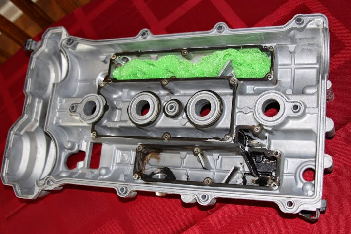
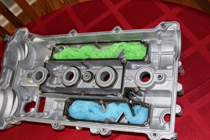
For now, here is what I did to my valve cover. I read somewhere on Mnet a couple years ago that people were filling the chambers with steel wool to help remove the oil vapors from the air being pulled through the PCV system. I felt like plastic was a better foreign material to have in my engine than steel wool. I DID clean off the old RTV and used Hondabond to seal the cover plates.
I will be using a catch can with AN-10 lines. I am also installing a flat top manifold/Skunks TB/D585 LS2 truck coils and working OP gauge at this time.
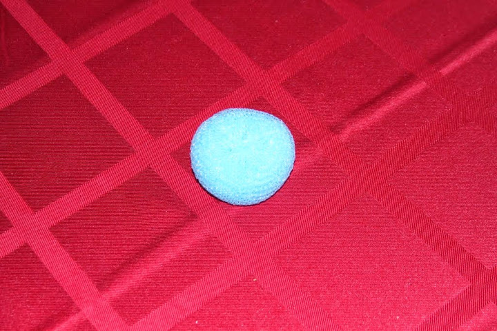
So I took one of these (plastic dish scrubbers)
Cut it to allow it to open up. Then I removed all the loose pieces that came from cutting it.....
Then I spread it out in the baffle chamber
And
Tired of turbo nuts backing off I have pulled the car into the shop for some work. Will show details of my solution for keeping my nuts where I want them later in the week when I get it back from the water jets......
For now, here is what I did to my valve cover. I read somewhere on Mnet a couple years ago that people were filling the chambers with steel wool to help remove the oil vapors from the air being pulled through the PCV system. I felt like plastic was a better foreign material to have in my engine than steel wool. I DID clean off the old RTV and used Hondabond to seal the cover plates.
I will be using a catch can with AN-10 lines. I am also installing a flat top manifold/Skunks TB/D585 LS2 truck coils and working OP gauge at this time.
So I took one of these (plastic dish scrubbers)
Cut it to allow it to open up. Then I removed all the loose pieces that came from cutting it.....
Then I spread it out in the baffle chamber
And
Reply
0
0
 04-14-2014, 01:44 PM
#38
Senior Member
Thread Starter
iTrader: (2)
Join Date: Oct 2011
Location: Hickory, NC
Posts: 675
Total Cats: 9
If so, did his **** melt?
I didn't even think about that. I figured they survive a dishwasher but that is only about 190�. I will test the melting point of these before install. Thanks for looking out for me!
I didn't even think about that. I figured they survive a dishwasher but that is only about 190�. I will test the melting point of these before install. Thanks for looking out for me!
Reply
0
0
04-14-2014, 02:43 PM
#40
Senior Member
Thread Starter
iTrader: (2)
Join Date: Oct 2011
Location: Hickory, NC
Posts: 675
Total Cats: 9
Oven is warming up now. Figured I would start at 250, then go to 275, and finally 300. I figure if it will take 250-275 it should be fine. What are your thoughts?
Reply
0
0


