When you click on links to various merchants on this site and make a purchase, this can result in this site earning a commission. Affiliate programs and affiliations include, but are not limited to, the eBay Partner Network.
Thanks for checking out the post. As you know, it's a long process. I'm finally seeing light at the end of the tunnel & getting excited about actually being able to drive her! Fingers crossed it's late spring...although early summer is probably what will happen. HA!
BTW...Those baffles you created for your oil pan windage tray were really cool. (I gave you a cat, but probably should have left a message.) You will have to let us know how they work out for you!
Thanks! It was a bitch to make and I get why oil pan baffle systems are usually around $250. I did request Improved Racing make one for the LFX and they said they would look into putting it into their design que. No promises though and no idea how long it might take, but maybe one day!
Griff did mention the ATS-V LF4 windage tray comes with a baffle and it is what they used in the cadillac LF4 race car. So if it is good enough for them...
Great info on those windage trays. Are you / Griff thinking the LF4 / ATS-V tray will fit the LFX? That would be the easy button. Honestly, I'm more worried about the oil pan being 3/4 of an inch lower than the subframe right now. (Although first time I starve the engine of oil, I may rethink that.) I'm thinking I might see if someone (Andrew @ Keisler maybe?) can make a modified oil pan, since V8R isn't making them anymore. I've been thinking about this for a while now, but put it on the back burner since my goal is to get the car running right now. Anyway, If I can find someone, would you be interested in a pan too? It might help get someone to make them if they are making more than just a single one off.
Steering Column
This should be a short & sweet write up. Before bolting the steering column back into the car, I had a couple little things to do.
First step , was to remove the steering lock / ignition switch. I decide a long time ago I was going to have a push button start. Probably after the 4th time that I had my helmet, hans, harnesses, and steering wheel all "on" and realized my car key was still in my damn pants pocket. Or just fumbling to find the damn keyhole when all strapped in. Either way...I'm all about making life simpler!
To get the ignition switch off the column, I thought I would need to drill out these two rivets. Somewhere along the way or drilling them out, I realized they needed to be spun out and actually screwed into place. So easy enough, dremel came out and put slots in them instead. They actually are very easy to back out once you realize they are threaded.
From there, I pulled out the grinder & removed a little more metal used to hold all of the wires around the steering column that was no longer needed.
With that done, some rust removal, a quick cleaning & tape up...and she was brought outside to my "paint booth" for a quick spray of primer & then black paint.
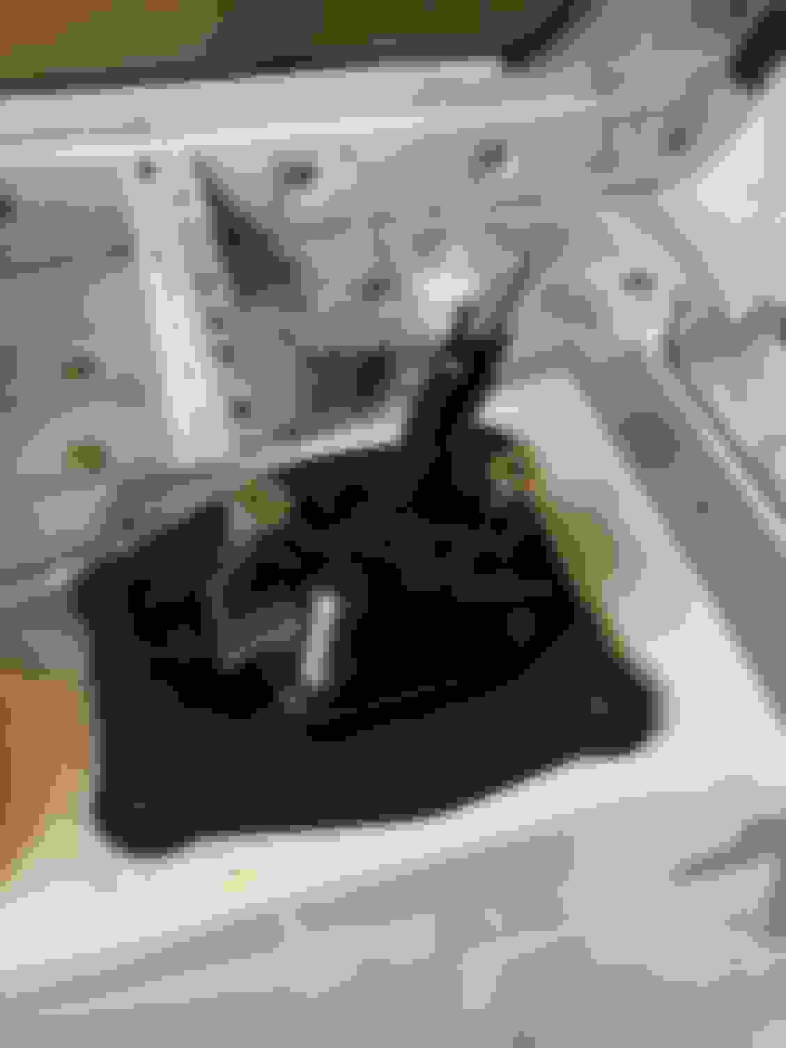
Install was simple enough...2 bolts at the firewall, 2 that hold it to the dash bar, and the universal joint coupler down at the engine. (Crappy photo sorry...but then again, it's just a steering column, so nothing that sexy to see anyway.)
Now I just need to buy a hub, quick disconnect, and steering wheel. I might hold off on the steering wheel & try my 330mm Momo from my other car to see if I'm good with the smaller size wheel with the manual rack. I really liked how much room it gave my legs. I know a 350mm is smaller than the stock wheel, but unsure if it will give me enough leg space. OR I might just need to add a spacer to put the wheel closer to me & use the 350mm.
Great info on those windage trays. Are you / Griff thinking the LF4 / ATS-V tray will fit the LFX? That would be the easy button. Honestly, I'm more worried about the oil pan being 3/4 of an inch lower than the subframe right now. (Although first time I starve the engine of oil, I may rethink that.) I'm thinking I might see if someone (Andrew @ Keisler maybe?) can make a modified oil pan, since V8R isn't making them anymore. I've been thinking about this for a while now, but put it on the back burner since my goal is to get the car running right now. Anyway, If I can find someone, would you be interested in a pan too? It might help get someone to make them if they are making more than just a single one off.
I have a full depth camaro oil pan and have had zero issues even street driving. Nothing has ever touched it and I am only 4.5" off the ground at the exocet frame.
Griff mentioned to me he was using an LF4 windage tray with a baffle built in and he just had to drill one bolt hole on it to get it to fit.
The part number is below. Genuine GM Oil Deflector 12657086
I would personally risk the oil pan being too low versus removing oil from it.
I'll be picking one up for the next time I have the engine open too. Thanks for the number! That's definitely the easy button.
I'm also glad to hear you haven't had any issues with the oil pan being a little low. I plan on running this pan for a little while...I need to drive the car some before pulling the engine!
That said...I had 2 off a year ago at Road Atlanta (10B) and there is a serious rut (more like a ditch) that I bottomed out my car in pretty hard, and scraped along before popping back out...No real damage / I kept going, but I think about what if I did that with the LFX? My day would most likely have come to an end (and been that guy with oil on the track, causing everyone else to loose track time.) I'm not worried about losing a half quart maybe one quart's worth of oil space, mainly because I plan on putting an oil cooler on the car and that should add the oil back / will also keep the oil temps within range.
While I was working on the dash & steering column, I also worked on the shifter & got that installed. I spent a lot more time on the shifter than I would have ever thought, and frankly, I'm a bit disappointed in the end results. Maybe all will be well when I start to drive the car.
Anyway, I paid V8R to modify the Camaro shifter to work with the Miata, now they sell an aftermarket short shifter, which I hear is good. I had mine modified before V8R switched over to the aftermarket short shifter. I figured I'd try my modified one, and if when I don't like it, I can always upgrade later.
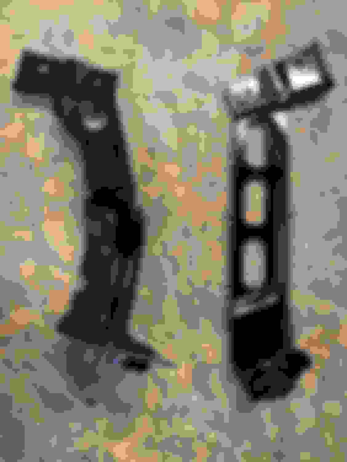
I sent the following parts off to V8R (I actually cut some long ears off the two ends of the shifter housing before sending.)
And the following came back...(you can tell the shift linkage & shifter are both shorter now...and a "plate" has been welded to the shifter base)
Unfortunately the shifter bushing was returned broken...it probably would have worked fine as is, but I didn't want to have the bushing fail after everything was together and need to replace it. It's always tight between the transmission tunnel, the transmission, and the shifter.
So I found someone online who would make derlin bushings and sent him the measurements for what I needed. Unfortunately, what I gave and what I got were off by just enough to keep the pin from being able to be installed.
I was going to send it back to be fixed / have another new one made (along with my original parts this time) when Sean from Sadfab reached out to me saying my bronze bearing kit was ready and to send him my poly bushings that needed to be drilled out. I asked if he could also "fix" my derlin bushing I had made and Sean said yes and I sent all of those parts to him too. When I got my stuff back, the new bushing fit now. Happy boy!
From there, everything basically sat on a shelf for over a year until mid Oct 2020 (when I did this work). The shifter assembly definitely isn't going to win any beauty contests. I wasn't sure if I was going to try and cover it all up or just let it be...but either way, I decided a coat of paint might help hide some of it's ugliness. So out to the paint booth it went where it was painted with the steering column etc.
With some pictures & the parts from before I pulled it all apart, I put everything back together again...(those springs are a pain in the ***...most people don't seem to be using them...the reason is that the original shifter the springs connected to a skinnier area, than the modified shifter. I sort of forced them in place, we will see how well that works in the long term.)
Original shifter before being all taken apart (Notice the springs sit on the skinny area)
Bottom of shifter after re-assembly
Shifter back together...in the car & with some paint.
I also messed a hole bunch with the rubber boot that came with the Camaro shifter. I was trying to find something that would fill up the hole and possibly keep the temp down a bit. The rubber boot from the Camaro when installed backwards, just almost fit, but was just a little too big on the front most edge.
Here it is without the shifter assembly in place placed in backwards. The shifter assembly makes the front edge come up just enough that you think you can mash it down and make it all fit, but you can't...it pops back up.
Funny enough, it dawned on me that the Miata one might just fit and it attaches to the center console, not the base of the shifter. It's a bit tight in the forward gears, but will work. I also stuck the old "5 speed" **** from the old Miata shifter on it for now.
You can see how it stretches the boot a bit, but it works. (this is 3rd gear btw...notice how close it is to the "Tombstone")
Now for my disappointment. The "down gears" 2, 4, 6 are all straight up were neutral should be. The neutral "area" is where the "top gears" R, 1, 3, 5 should be & as you can guess, the top gears are very forward...making me wonder how much I'm going to hit the switches on the switch panel in front of it.
This is 4th gear
This is neutral
This is 3rd gear
This might not be an issue / I get use to it very fast, but it's obviously not right. I can probably pull it back out, cut it shorter and weld it back (I think this part was steel) or just buy the "new" short shifter that V8R sells, although I'm starting to feel like this is a "fool me once, shame on you, fool me twice, shame on me" type of situations. Anyway...For now, I'm going to roll with it. I'll decide if it's a real issue or not once I actually use it some.
With the steering in place, it was time to stick the radiator in and to figure out how everything was going to fit between the engine & the radiator. I quickly realized the next piece that needed to be installed was the Sway Bar. It's another piece that really only has one place it can be and the coolant hoses would have to work around it.
So I pulled out the sway bar I bought what feels like forever ago (actually purchased it before I even purchased the car. HA!) It's the big boy Racingbeat 1.25" diameter. As I pulled it out of the box, I started to wonder if I went too big here, but it's going on the car now, and we will see.
I figured this would be a quick install / didn't even require a post about, but like a lot of those "this should be a quick 10 minute job" it wasn't. I quickly learned that the Heavy Duty Sway Bar mounts that I had purchased from V8R (and already welded onto the frame of the car & painted) have mounting holes that do not work with Miata sway bar spacing. Why a Miata specific part doesn't have OEM spacing for the mounting holes that fit easily 95% of the bars people use on Miatas is beyond me...
This is the OEM sway bar bracket
(I know this all reads like I did it all at once, but I actually installed the bar where I wanted it using just one hole on each side so I knew where it would live, and did the rest of these steps below over the next couple of months...)
You can buy slotted sway bar brackets, and I thought about going that direction, but the Racingbeat brackets on the big boy bar are thick allowing the bolts to give support all the way up each side.
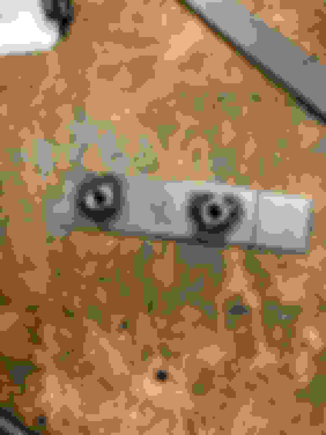
Since I thought best to use the reinforced brackets supplied by RacingBeat, it left me with drilling an extra hole in the V8R HD Sway Bar Mounts. I played around a little bit, seeing where exactly I wanted the bar. I tried to get it so that the end links would be 90 degrees to the bar and ended up with the bar pretty close and I used one of the existing holes and drilled one new hole on each side.
I should be beaten for how off center this hole is...
Getting my big paw into the mounts to hold a nut is a pain in the *** & with the extra hole, I wanted a better support for the backside, so I cut some metal backing strips and welded some nuts on them thinking this would solve my issue.
I didn't think much about my trash can being right next to my bench filled with a roll of used paper towels covered in mineral spirits and that nasty tar stuff used on our doors to hold the plastic barrier on, but I should have.
This nasty *** gooey tar stuff...I scrapped it off and then used paper towels and mineral spirits to get the rest off
The story gets interesting when I pulled my welding helmet off after my last tack weld and saw a small camp fire in my trash can. It wasn't huge, so I tried snuffing it out with my gloved hands...That didn't work and only caused the fire to get larger. I had a fire extinguisher only 3 feet away, but I didn't want to use it and make a mess, this wasn't a "real" fire (stupid man brain at work here) so I grabbed the trash can and dragged it outside to the driveway to use the hose on it. (While the flames only got bigger...about 1 foot over the top of the can now.) Of course, I happen to live in a townhouse in the city, and I have all 4 of my parking spaces (two in the garage, two in my driveway) filled with cars. So I had the can now sitting between all 4 of my cars and racing to hook up the garden hose, but my truck is blocking the hose spigot & I'm fumbling to reach it. As I fumble, I keep looking back at the can, and the flames are now 2 feet tall over the top of the can and growing. Now I'm actually worried. I abandon trying to get the hose hooked up and go flip over the can, hoping to slow down the fire. HA! OK, My little man brain has now decided that I'm OK with a mess & this does require the fire extinguisher. Of course I struggle to get the damn thing off the wall until I bent the bracket and rip it off the wall. I'm sure this was only 3 seconds worth of struggle, but it felt like 10 minutes had gone by. The real drama was over the fire extinguisher worked at putting out most of the fire, and I had time to get the hose attached and water down what was smoldering when I was done.
(Sorry no action shots of the actual fire...I was a little busy...LOL)
Funny, you would have never guessed the can was half filled with trash looking at what little was left. After cleaning up my dumpster fire, I decided I was done for the night. A few days later I finished things up & painted them.
I used my stock bracket to make these, so I wouldn't burn off the paint on the Racing Beat brackets when I welded them, but when it came time to install, both were a tiny bit off and wouldn�t thread the bolts 100% down. I no longer wonder why...Ever have that feeling something is fighting you the entire way?!?
I thought about building new ones, but I didn�t want to waste more time on them�so I cut each one in half and used them that way instead.
I spent a lot of time figuring out the cooling starting around Halloween 2020 and I basically finished up all the coolant stuff last week (March 2021). I didn't spend 4 months working only on it. I'd do some work on it, do something else, order a few more parts etc. That all said, this isn't going to read like I took that much time or effort on the cooling system, but I probably have 3 weeks / a months worth of work getting it all sorted, with some of it as throw away. I'm certain if I was to do this over again, I would probably have everything done in a week, but aren't we always faster the second time around?
Let's discuss Radiators, since that's the heart of any cooling system. The LFX and the BP use two completely different sides for the coolant hoses. Meaning if you use a "Miata" radiator, your going to have to cross the hoses over to the other side of the engine bay. You can also go and buy a generic radiator with the inlet/outlet on the correct side, but then you still have to figure out hoses and you will need to figure out mounting too. One other consideration, is that the LFX has a steam port & uses an expansion tank, so you don't need (or want) the fill neck on your radiator anymore, since it's not the highest point in the system.
After some consideration, I decided upon the devil I know, and went with a Supermiata radiator (which I really like) and I'd figure out how I wanted to cross the lines / deal with the fill neck.
NOTE: If someone else is about to do all of this...take a moment and look seriously at the RX8 radiator, I noticed this about a month ago, once I was well down my path. I believe its the right size, just one inch shorter in height, uses the NB style mounting for the bottom, and the inlet / outlet are in the “correct" spots & no fill neck. I believe it will fit and work with only needing to figure out how to mount the top of the radiator in place & hoses. <--That all said, do your homework, this was just a first glance look.
Since "racecar" with no AC / condenser to worry about I decided to only run one fan. I figured I would run a stock fan and see how that works. If I need more, I'll upgrade to a Spal fan. So I put the primary fan on (it's a tiny bit larger) and installed the radiator.
The LFX has a TON of space up front between the engine & the radiator, but unfortunately it’s very misleading. The water pump outlet and the throttle body both hang out past the engine about six inches and makes it unusable space.
The water pump outlet actually protrudes a little further out past the throttle body, you just can't tell in this picture...but lots of room otherwise. A top down showing all that space & better look at the water pump outlet
As you can see here, the fan is just 2.25” away from the water pump outlet on the engine.
So I decided to move the radiator forward about an inch at the bottom (I stuck it in the holes that the condenser normally occupy) and that gave a little more room between the water pump outlet and the fan (sorry, I didn’t take a measurement like I should have.)
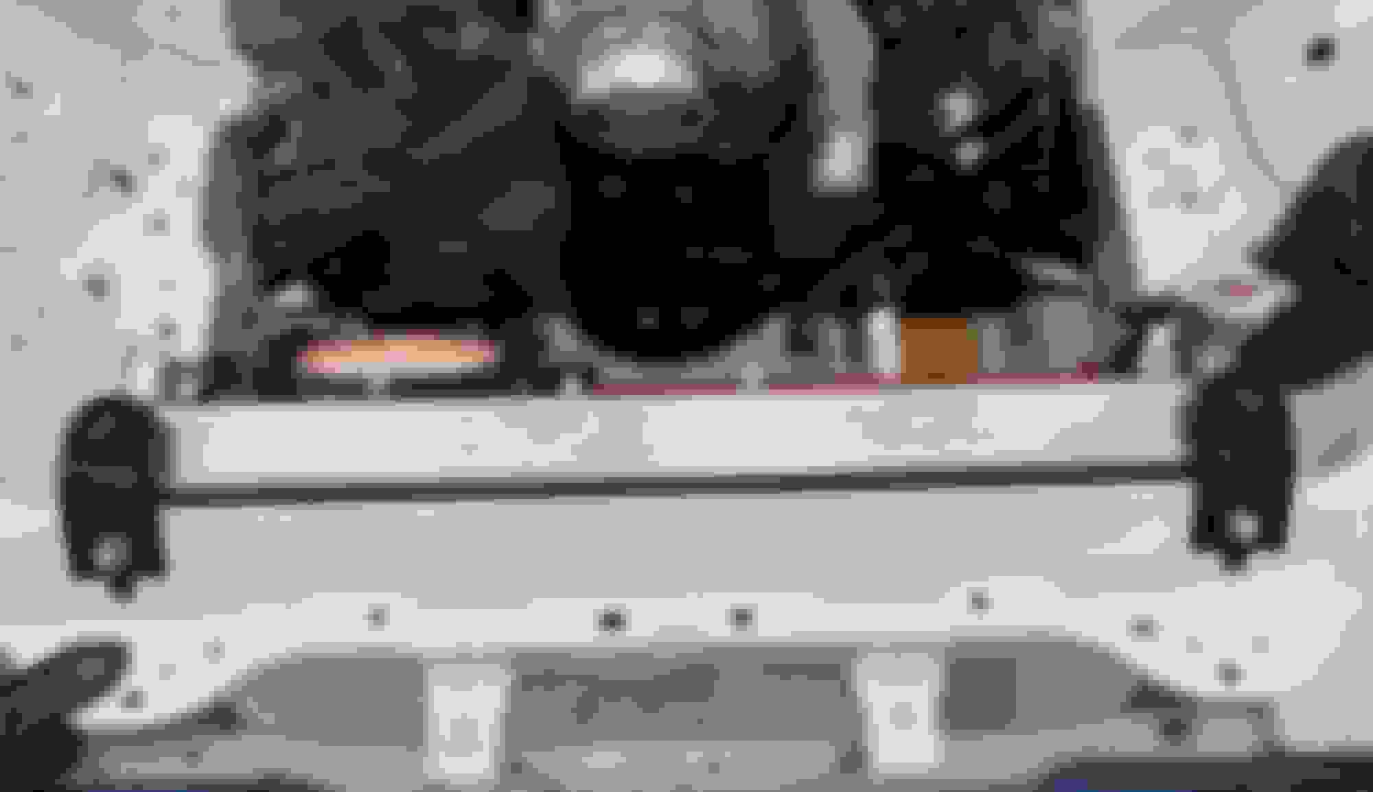
The water pump outlet & throttle body also point downward, and that angle also takes up some room. I still wasn’t sure if this was enough space & got the idea to make some fake hoses out of some 1.5” PVC I had lying around to check if I had enough space / placement. I figured it’s larger than the 1.25” the hoses are (well the outlet at the front of the engine is 1.5” so same size there) and if it would fit, a rubber hose shouldn’t have an issue.
Close, but looks like it will work
This also allowed me to check to see if the sway bar would be in the way or not from the coolant tube that connects to the back of the engine. At this time I thought I could modify and use the one that came with the Camaro and connects above the alternator (later I’ll realize this isn’t as easy as I was hoping and swapped to a LFX Caddy pipe that Gooflophaze found that connects below the alternator).
Along with the long run of "pvc hose", if you look at the radiator mount, you can see the radiator is actually in the condenser hole right now. That gave a little more room between the coolant neck and fan since it angled it a bit further away.
It looked like it will all fit. Although I was a bit concerned about supporting this hose...it's a pretty long stretch going "diagonally" across the engine.
I went a little crazy and pulled out some crappy red vacuum tube that the previous owner used on the BP engine to "dress it up”....not to mention all the chrome bits I keep removing. Anyway, I put that crap tube to good use simulating how I was going to handle the steam port & the expansion tank. This was more for a buddy that I was talking to about all of this & ultimately I changed up the idea and did not connect the radiator overflow into the steam port, but the rest of the flow is all correct with the steam port going to the expansion tank (the washer bottle in the picture below) and the expansion tank connected to the coolant tube at the back of the engine (it's the same tube that exits above the alternator).
So, I had somewhat a plan on how all of this was going to be installed...time to start making it happen.
(Sorry no action shots of the actual fire...I was a little busy...LOL)
Funny, you would have never guessed the can was half filled with trash looking at what little was left. .
Good thing you didn't have a real fire, that WD40 can could have made things real exciting.
.
I used my stock bracket to make these, so I wouldn't burn off the paint on the Racing Beat brackets when I welded them, but when it came time to install, both were a tiny bit off and wouldn�t thread the bolts 100% down. I no longer wonder why...Ever have that feeling something is fighting you the entire way?!?
.
I have used those RB mounts/bars on three NBs, and never had a problem. Maybe the trouble lies in the stock mount, it may have opened a bit?
There was actually 2 cans of WD40 in there! The other one rolled under the truck when I flipped the trash an over. They were both half filled, but wouldn’t spray anymore & had been sitting on my shelf for a while, so I finally tossed them. But yes! That would have been exciting! I’ve had a few fires in the garage over the years (a couple were actual engine fires...one a carburetor and the other from a power steering hose) none of those got me that excited...this one definitely got my attention.
I think you are 100% right with that bracket. I just never lined the two up until after I made those two pieces and they didn’t fit. I should have checked beforehand. Rookie mistake on my part.
I had moved the bottom of the radiator to the condenser holes in the mounts to give me a little more space. Only issue is that the condenser holes, are a bit more oblong and not the right size for the radiator. You could probably stick the radiator in these holes and send it, but I don’t want to worry about it, especially on the track. So, I needed to modify the mounts.
I cut off the bottom piece and then moved it forward to the next indention and spot welded back. This moved my radiator mount hole forward to were the condenser hole use to live…about an inch forward.
Notice how the condenser hole is more elliptical vs the radiator hole. I just used the little indentations to move everything forward. (Passenger side mount)
I test fitted it to check to see how well it would work. (Drivers Side Mount)
Once I knew it fit well, I cut down / removed the half of the bracket that was no longer being used and removed the condenser part of the bracket too.
(Drivers Side Mount)
(Passenger Side Mount)
I also added a little reinforcement along the edges to add back some strength.
(Drivers Side Mount)
Between the two, I removed a little over half a pound too!
A little paint and ready to be reinstalled.
About a month later (Dec 31st 2020) I tried fitting the air intake…It was close to fitting, but was rubbing on the fan. I did a little research online and found that the AC fan (which is a little smaller) blows almost the same as the main fan (80 cfm difference) so I swapped fans. That also gave me more room with the water pump outlet which was a double win in my book. There was now about 1/8” between the intake and the fan stud on the radiator, but it was still going to rub.
I thought about cutting that fan stud off, but I might need a second fan, and instead decided to move the top of the radiator forward a little bit. I didn’t need much, so I bent the metal back across the lip of the radiator support to get another half an inch of room. I did this by heating the metal with a heat gun and using a crescent wrench to slowly bend the metal back. Luckily, I didn’t mess up the new paint.
You can see the bend is half way done here...Also, you can see the lower mounts in this pic, just not painted yet.
Once the metal was all bent, I test fit the radiator again and had enough room to not worry about rubbing any longer.
I now needed to modify the upper radiator brackets so it would hold the radiator forward. I decided to cut out the “square” in the center of each bracket and weld them back together, guessing that was the right amount of space to remove. I just tack welded them on the backside first, and test fit.
I did clean the paint off before welding, I was just trying to get the right angle to weld them back at with the magnets first.
They needed a little more of a bend in them now…so I basically just bent them in place while installing to get the right amount of bend. That made them fit perfect.
They sat this way for a month or so before I finally welded them up front & back.
And a little grinder action to make me the welder I ain’t…
And a coat of paint later and I doubt even the die hard Miata guys would even notice.
True to the Miata form, it’s a game of millimeters when trying to fit things and the radiator proved to be the same even with all that room between it and then engine. If I was to do this all over again, I would start at the top of the radiator and see if moving it gave me the space I needed on it's own.
Thanks! It was a bitch to make and I get why oil pan baffle systems are usually around $250. I did request Improved Racing make one for the LFX and they said they would look into putting it into their design que. No promises though and no idea how long it might take, but maybe one day!
Griff did mention the ATS-V LF4 windage tray comes with a baffle and it is what they used in the cadillac LF4 race car. So if it is good enough for them...
OK, I looked back but I did not see anything on the oil pan baffles. We've blown up 3 motors this month so far due to oil starvation under braking/cornering. We are designing a baffle with trap doors to see if it will work. What does yours look like?
Also, the transmission is crap. Super flimsy shift forks made of silly putty or something. And the clutch disc will shear the rivets just for fun.
https://www.facebook.com/1711940436/videos/10208186413894021/ Here's the link to the 2nd motor blowing up.
I saw your video on YouTube and I was a bit shocked on the engines having issues. (The clutch seems to be an issue with everyone.)
What weight oil are you running & any idea about temps? The LFX doesn’t have an oil temp, the ECU guesses it from other info and reports that “made up” number if you are looking / logging from the ECU. I plan on putting a temp gauge & cooler on mine, just haven’t yet. I’m slow compared to you all. Contact Andrew at Keisler Automation for a oil “plate” that easily allows for a cooler.
I saw that OEM clutch got shredded...think that was a one off? Luke G is also trying a “new” spec clutch, although I know others had a lot of issues with their previous spec clutches.
Love watching your cars...hate seeing the growing pains. Hope this helps a little.
Should have posted above...I don’t think Ryan Passey has messed with baffles in his oil pan & I know he was logging temps / put an oil cooler on his car. He’s doing TT, so I doubt getting the car as hot as your endurance racing, but fairly certain he’s sloshing the oil around just as much...you may want to reach out to him.
OK, I looked back but I did not see anything on the oil pan baffles. We've blown up 3 motors this month so far due to oil starvation under braking/cornering. We are designing a baffle with trap doors to see if it will work.
Two threads that are from the top builds using the LFX in a track based application that are must reads. They are both super nice as well and I'm sure will help with what they can if you reach out.
Should have posted above...I don’t think Ryan Passey has messed with baffles in his oil pan & I know he was logging temps / put an oil cooler on his car. He’s doing TT, so I doubt getting the car as hot as your endurance racing, but fairly certain he’s sloshing the oil around just as much...you may want to reach out to him.
Ryan and have messaged back and forth quite a bit over the last month or so.
we are seeing sustained 250 oil temps and 210 water temps. The temps are very sensitive to open vs turbulent air. Get behind a car and they start to rise almost immediately. Oh and we are running the Keisler oil plate.
we are running a setrab 625 oil cooler. Probably need to step that up a bit, run a higher weight of oil and add an Accusump.
we did tear down one of the trannies tonight. We found the forks are not the problem. There is too much of a gap in the selector forks. The selector was able to slip between the 3-4 gate and the 5-6 gate without disengaging 4th gear. Once it was in the neutral position in the 4-5 gate, the detents wouldn’t allow any more movement and it was stuck there.
Thanks for the info! Those are great data points to have. I'd definitely appreciate it if you report back with what changes you made / how successful they were.
Back to cooling...The LFX has a coolant tube that runs from the back of the block to the front (think coolant bypass on the BP.) There are a couple different versions of this tube depending upon what your donor vehicle was. The Camaro (donor vehicle of choice for this swap) runs this coolant tube across the top of the side of the engine and it comes out on top of the alternator. (We'll call this the "Upper passage" AKA "The Donner Party Passage".) This requires you to run a coolant hose diagonally across the front of the engine to get to the radiator I'm running. Gooflophaze went through the Chevy parts bin and found an LFX tube from a Caddy that takes a lower passage & ends up below the alternator. (We'll call this the "Lower passage" AKA "Gooflophaze's No Need for Cannibalism Passage".) This setup only requires you to go across the front of the engine, thus a lot less rubber hose.
Upper Passage...
Maybe I've been reading too much Robert Frost since Covid has locked us all down, but I thought "The road less traveled" would be relatively easy. The tube actually fit in place and it would even bolt up, but it was just barely touching the side of the engine bay.
You can see where I tried heating the pipe up and bending it here too...
It looked like it only needed to be bent up a little bit (half an inch) to keep it from touching. So, I attempted to heat up the bar and bend it. Unfortunately, I don't have a torch, the best I have is some MAP gas. I tried my best to heat up the tube enough to bend it, but after trying a couple times even with someone helping me (i.e. keeping the heat on it while I try to bend it) it wasn't budging. (See photo above for where I tried to heat it up.)
A smarter man would have punted and gone and bought the "Easy Peasy" coolant tube, but we are not quitters & I have a grinder & a welder...So, I thought I was clever and cut the inside of the tube where I wanted to bend it about 80 % of the way and then bent the tube up to close the gap. I did this a few times and success! The tube no longer touched.
Cutting the pipe / bending it. Here I'm tack welding it back a little bit
Success?!?! No longer touching...but now everything else forward needs to be "moved" back
For some reason, I wasn't thinking that if I bent the pipe up at the back of the motor 1/2" what that movement would translate into at the front of the motor. Now I needed to bend the pipe down up front. After making these cuts and moving the bar some more, I now had the outlet pointing the pipe down again, but directly at the sway bar. I messed with this some more taking it on and off all while making more cuts until my inner Susan Powter cried out "Stop the Insanity"! It was time to take the road more traveled... "The Lower Passage".
If you look closely, you can see I had cut the pipe a bunch of times...I think I actually cut it a couple more times than what you can see here before I decided to stick a fork in it.
Lower Passage...
This is the pipe you want to buy --> 2014 CTS pipe - PN 12635783 (Thanks Gooflophaze!) This pipe does need some modifications too, but you can immediately tell its a much better fitment. First, the pipe is out of the way giving you more room up top & second it exits below the alternator and makes the rubber hose length needed to connect to the radiator a straight shot across. Much Easier.
It's not installed all the way here, because it would hit the sway bar otherwise, but you can see the much better exit below the alternator vs above it.
The first thing you have to change about this pipe (super easy) is you need to cut off some of the extra metal used as mounting points for I'm guessing a wiring harness or something else. With these cut off, the tube is much easier to install and remove.
You can see the one tab is hitting the valve cover keeping it from fitting right
Those two tabs removed...MUCH easier to install now.
Once you make the change above, your next challenge is that it points directly at the sway bar. (You can semi see that in a picture above) Gooflophaze fixed this by pulling out the blue torch and bending the pipe. From before, I knew that wasn't going to work for me. I also didn't really want the horror film of slashing up this tube and welding a bunch like I did to the last tube. Looking at it some, I realized that the only thing keeping the tube from not pointing at the sway bar and pointing a little lower was the upper mount that is there to keep the tube from popping out of the back of the motor. If I could just move it 3/8" around the pipe...
The bolt (going through what I am calling a mount) is holding the tube in place in this picture. BTW...This area SUCKS to get your hand or any tool into, & EVERYTHING seems to connect back in this little corner.
The other mount (that we just cut those tabs off) could be bent a little bit. I thought about just drilling out the hole and making it more of a slot, but I didn't think there would be enough metal left over, so instead I cut it off and moved it 3/8" around. This made it so the tube would point under the sway bar vs directly at it.
Almost cut all off
Repositioned in the correct spot & ready to weld back (I actually did this a couple times...I moved it too far one time, and another time my spot weld wasn't enough while I was installing it and it fell off.) Welded up where she belongs now.
There is one more mounting point for this tube. It's a clamp at the other end. Again, no need to reinvent the wheel. I followed Gooflophaze's path and bent / moved the clamp over and mounted it to the bottom of the alternator bracket. there is a convenient threaded hole there that you can use.
I don't have a bolt holding it in place in this picture, but you get the idea.
One last modification for this pipe. I needed to add a hose barb to the pipe. This will be where the expansion tank dumps fluid back into the system. I ugly welded this 3/8” hose barb to the pipe. If I was to do this again, I think I would have gone with a 1/2” barb, but this should work. More info on how the expansion tank is set up and works in a future write up.
My pilot hole, I used a step bit to drill out the hole the rest of the way.
Barb sitting over the hole
All welded up...
I painted the tube where I had done the modifications to keep it from rusting and job done for this part. Here is the finished tube in place.


 0
0