
BMW Pierburg Electric Waterpump Controller
 11-13-2012, 09:18 AM
#1
Elite Member

Thread Starter
iTrader: (9)
Join Date: Jun 2006
Location: Chesterfield, NJ
Posts: 6,898
Total Cats: 399
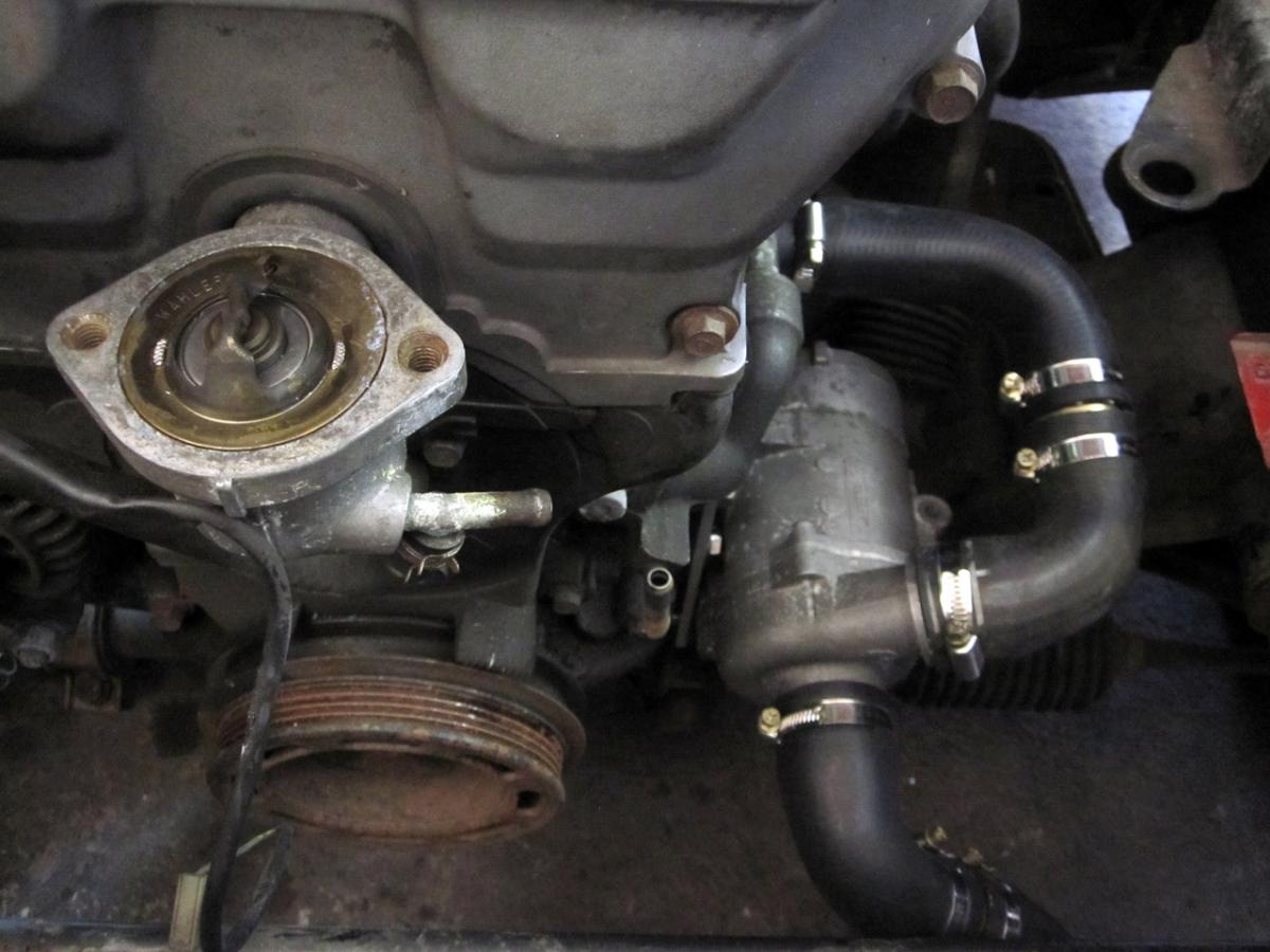
On my V6 swap I am running a BMW/Pierburg CWA200 Electric Waterpump. It works on my no undertray/ebay fan & alum radiator street car but should also work great for track cars with proper/typical radiator airflow parts installed. I am not sure how much HP the mechanical WP sucks up but it is nice to be able to run the waterpump when the engine is off, or at a speed that is dictated by engine temps and not engine rpm.
Perhaps run a reverse flow coolant system.
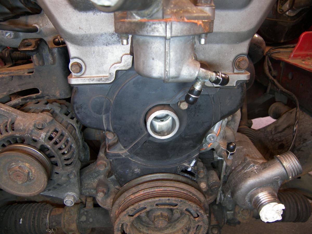
Clean up the front of the engine... I only have one belt driven accessory, the alternator.
Here's mine:

These can be found for the cost of typical electric waterpumps. Or you can be stupid lucky like me and get it in exchange for welding some pipes together. Now it's not like your typical DC electric motor where 2 wires get the job done; this bitch needs a +12v PWM signal to control the speed (I have the specs from Pierburg if anyone wants them). Well, you can run the thing at full speed without the PWM signal but one of the benefits of an electric waterpump is the ability to slow it down. And at 100% duty cycle, the water flowing thru the various cooling hoses makes a hell of a racket.
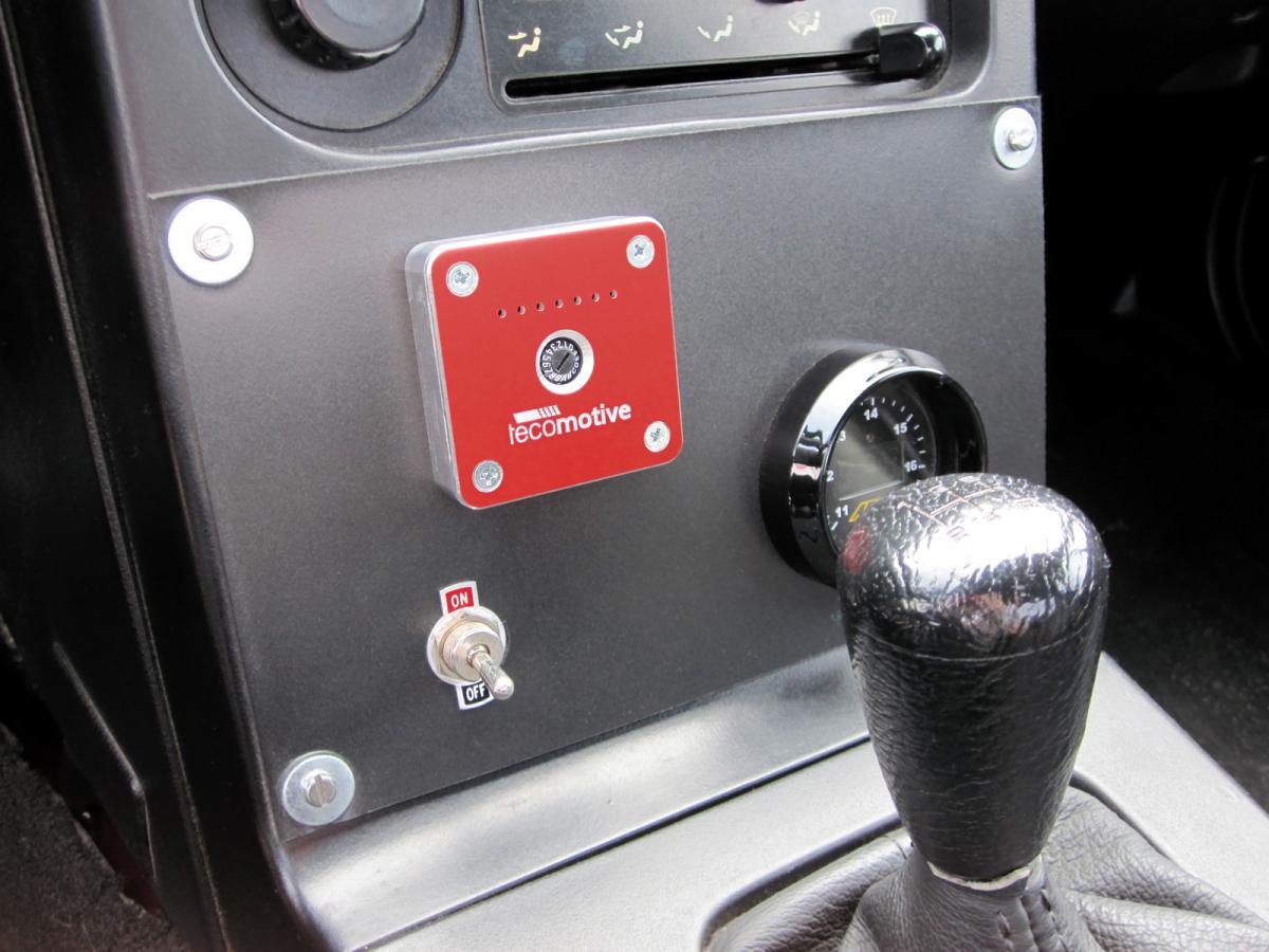
My series 1 AEM EMS has a user definable PWM output which makes life easy. However, for those needing a stand alone controller for this pump, this fella makes it. The Tecomotive TinyCWA:
Tecomotive
tinyCWA
PDF manual:
http://www.tecomotive.com/download/manual_tinyCWA.pdf
Pics of the pump on his Miata test car. These worked at my home computer but won't show at work so i'll just post the links and hope for the best:
Perhaps run a reverse flow coolant system.
Clean up the front of the engine... I only have one belt driven accessory, the alternator.
Here's mine:
These can be found for the cost of typical electric waterpumps. Or you can be stupid lucky like me and get it in exchange for welding some pipes together. Now it's not like your typical DC electric motor where 2 wires get the job done; this bitch needs a +12v PWM signal to control the speed (I have the specs from Pierburg if anyone wants them). Well, you can run the thing at full speed without the PWM signal but one of the benefits of an electric waterpump is the ability to slow it down. And at 100% duty cycle, the water flowing thru the various cooling hoses makes a hell of a racket.
My series 1 AEM EMS has a user definable PWM output which makes life easy. However, for those needing a stand alone controller for this pump, this fella makes it. The Tecomotive TinyCWA:
Tecomotive
tinyCWA
PDF manual:
http://www.tecomotive.com/download/manual_tinyCWA.pdf
Pics of the pump on his Miata test car. These worked at my home computer but won't show at work so i'll just post the links and hope for the best:

Reply
 4
4

4
03-26-2013, 12:33 PM
#2
Newb

Join Date: Mar 2013
Posts: 1
Total Cats: 0
Hi TurboTim,
I have the CWA-400 water pump of Pierburg. The problem is that I can't "wake up" the water pump. Only 3 Amperes pass through the water pump, but it would be more or less 30 Amperes.
The water pump has 4 pins. The pin 3 is not used. Pins 2 and 4 are for power supply and pin 1 is for PWM.
Have you got any idea or any technical datasheet of CW400?
Thank's
Reply
0
0
03-26-2013, 03:12 PM
#3
Elite Member
Thread Starter
iTrader: (9)
Join Date: Jun 2006
Location: Chesterfield, NJ
Posts: 6,898
Total Cats: 399
Yes, I have two .pdf's that will make your life easy: A description of each of the 4 pins and what each needs to see in order to control the pump speed. I can email them to you. Cliff notes:
Pin 1 is battery voltage
Pin 2 is PWM signal
Pin 3 is a test/BSD signal
Pin 4 is Ground
Supplying +12volts to Pin 1 AND pin 2 (and grounding pin 4) should make it run full speed after a 'timeout' period of about 3-10 seconds. To vary speed based on PWM input on Pin 2, you need at least 3ms of an inturrupted high pulse in order for it to awake the pump. Keep that in mind when you decide on the PWM frequency and/or your duty cycle percents.
PM me your email address or email me at timmafod at gmail.
Last edited by TurboTim; 03-27-2013 at 11:12 AM.
Reply
0
0
 03-27-2013, 10:55 AM
#6
Elite Member

Join Date: Jul 2005
Posts: 6,420
Total Cats: 84
Thanks for posting the info Tim.
That controller is pretty slick.
What are said flaws you're gonna fix? I remember reading writeups on the GM reverse-flow system (which Evans of NPG coolant fame claims he invented), that some of the flaws are addressed by the use of NPG (no water, very high boiling point).
Does anyone know how BMWs pump water through the heater? Do they use a thermostat (bypass or otherwise) to maintain flow through the heater core? Knowing that the Germans tend to use 3 parts when 1 will do, I would expect them to use a 2nd, smaller pump for the heater core, and no thermostat.
That controller is pretty slick.
Does anyone know how BMWs pump water through the heater? Do they use a thermostat (bypass or otherwise) to maintain flow through the heater core? Knowing that the Germans tend to use 3 parts when 1 will do, I would expect them to use a 2nd, smaller pump for the heater core, and no thermostat.
Last edited by JasonC SBB; 03-27-2013 at 11:13 AM.
Reply
0
0
03-27-2013, 04:37 PM
#7
Currently I am feeding the front of the head. I plan on feeding both the front and back side of the head on the next go around. Also, I need to move the thermostat from the head to the front of the motor where water will now be exiting the block. I want to get a reading of the hottest water.
Another problem is that I was pulling hot water from the motor and pushing it into the radiator. It worked just fine, but I am afraid to shorten the life of the pump that way. I want to pull water from the radiator, through the pump, and then into the motor.
The next design will probably not look as good as the old set up, but should be much more efficient, and work well on any power adder motor.
Reply
0
0
03-27-2013, 05:13 PM
#9
Boost Pope

iTrader: (8)
Join Date: Sep 2005
Location: Chicago. (The less-murder part.)
Posts: 33,045
Total Cats: 6,607
If there is any significant amount of air in the cooling system, that air will tend to congregate in the upper radiator tank. If the quantity of air is sufficiently large, then the upper radiator port will become completely uncovered and the pump will be essentially air-locked.
With the bottom-draw design, the system is more fault-tolerant. It will continue to function, at a diminished capacity, with extremely large amounts of air in the system.

Reply
0
0
03-27-2013, 05:21 PM
#10
My pump has two outlets so feeding the front as well will be very easy. I would think this would create the most even distribution across all four cylinders as is possible.
I do have the oil filter cooler to think about, so I might just use one of the outlets to feed it, so feeding just the back of the head is not out of the question. In the meantime, I am thinking of a solution that will keep me from using one of the outlets for the oil cooler.
I do have the oil filter cooler to think about, so I might just use one of the outlets to feed it, so feeding just the back of the head is not out of the question. In the meantime, I am thinking of a solution that will keep me from using one of the outlets for the oil cooler.
Reply
0
0
03-27-2013, 05:30 PM
#11
This seems like it would introduce a potential fail-deadly scenario.
If there is any significant amount of air in the cooling system, that air will tend to congregate in the upper radiator tank. If the quantity of air is sufficiently large, then the upper radiator port will become completely uncovered and the pump will be essentially air-locked.
With the bottom-draw design, the system is more fault-tolerant. It will continue to function, at a diminished capacity, with extremely large amounts of air in the system.
I do currently pull water from the block and push it into the bottom of the radiator. I retain the stock water line from the top of the radiator to the front of the cylinder head. Even if the water level is somewhat low, it still flows. I do not know how low it can get before it stops circulating. I will fix it before I find out.
Reply
0
0
03-28-2013, 02:09 PM
#13

This makes me drool. I want to put the radiator back were the fuel tank used to sit. Mainly because I want a louvered "package" shelf that I've built with "CAUTION HOT" stickers around it on the XP car.
My concern with the factory pump is pulling/pushing water all that way. Sounds like this sucker has plenty of oomph to make that moot.
My concern with the factory pump is pulling/pushing water all that way. Sounds like this sucker has plenty of oomph to make that moot.
Reply
0
0
05-16-2013, 11:56 AM
#14
Newb

Join Date: May 2013
Posts: 3
Total Cats: 0
I have pierberg pump., I would like to know. If the battery is connected to the 12 volt battery will need to be around the top, I did not bring it to the car. I will bring it to the solar cells.I thank you for the answer.
Reply
0
0


Thread
Thread Starter
Forum
Replies
Last Post
Zaphod
MEGAsquirt
47
10-26-2018 11:00 PM
russian
Miata parts for sale/trade
6
10-08-2015 03:01 PM


