
Miata LFX Swap (Singular Motorsports & Good-Win Racing)
 03-23-2017, 09:41 AM
#501
where did you get the mini relays for the cooper bussman? i wanted to use that box but got hung up on where to buy the relays.
__________________
OG Racing
Your Source For Motorsports Safety Equipment
WWW.OGRACING.COM
800.934.9112
703.430.3303
info@ogracing.com
OG Racing
Your Source For Motorsports Safety Equipment
WWW.OGRACING.COM
800.934.9112
703.430.3303
info@ogracing.com

Reply
 -1
-1

-1
03-23-2017, 01:20 PM
#502
Senior Member

Join Date: May 2007
Location: Atlanta
Posts: 997
Total Cats: 156
https://www.delcity.net/store/ISO-28...91799.h_791806 is where I purchased a lot of our wiring components (we also used the same bussmann box).
Relays are also pretty common - you can get a handful in a junkyard from GM section.
Relays are also pretty common - you can get a handful in a junkyard from GM section.
Reply
0
0
 03-24-2017, 03:03 AM
#504
Supporting Vendor

Thread Starter
iTrader: (3)

Join Date: Jul 2006
Location: San Diego
Posts: 3,303
Total Cats: 1,216
Switching gears a bit, this car will need some serious brakes... and they arrived 
Details on this kit are in the Race Prep section, newly released V8R 11.75" BBK with Stoptech billet STR42 caliper. Ohhhh yeah baby, track testing can't come soon enough!
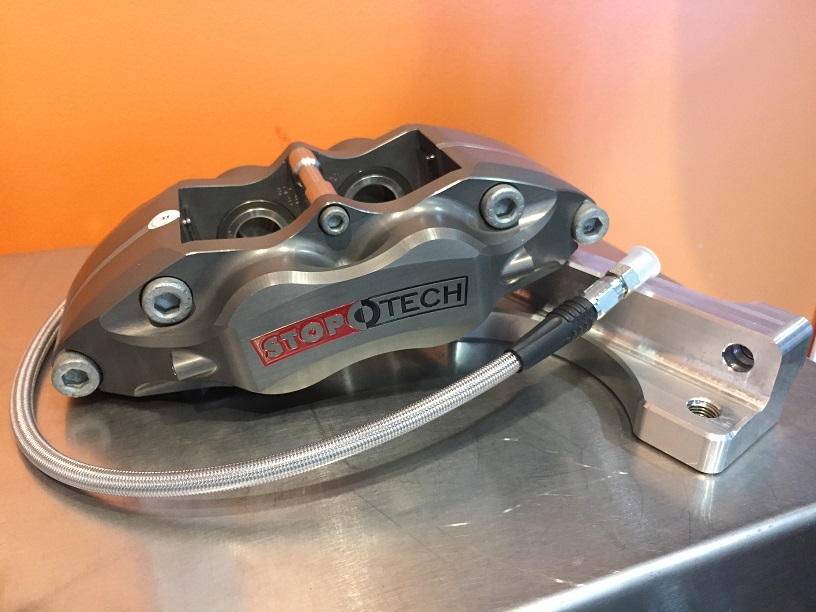
Paired with my AP Racing J-hook rotors on V8R hats:

Details on this kit are in the Race Prep section, newly released V8R 11.75" BBK with Stoptech billet STR42 caliper. Ohhhh yeah baby, track testing can't come soon enough!
Paired with my AP Racing J-hook rotors on V8R hats:
Reply
3
3
 03-24-2017, 08:35 PM
#507

Great work! What software did you use for harness layout? Kapton, service loops, mostly high quality parts, good wire choice, etc.
But Weatherpack as the chosen interconnect series? Ah, my eyes, my eyes, they are burning! I mean, this is like going out and recording Planet Earth II quality cinematography and then showing it to people on a 15" CRT from 1997 in a theater.
The simplest way I explain this to people, who often think weatherpack = any sealed connection, is that Weatherpack is a 70s/80s era design from Delphi superseded by Metripack from the 80s/90s which was then superseded by GT in the 2000s. The supersesions were warranted and no new project should ever use weatherpacks imo. Their only place in modern wiring is for existing connections which cannot be easily changed, eg device connections. So, what to use? Deutsch DTM, DT, DTP is a solid choice. Molex MX series. Delphi GT series. Bulkhead options are common. Or talk to us at bmotorsports.com about it. Even the stock Miata connections are a leap ahead of Weatherpack in design.
Every other part of the work I see is excellent except the crimping which has excessive strip lengths and not using a positive wire stop, allowing the conductor too far past the crimp joint and also allowing the insulation too close to the bellmouth at the rear of the crimp. See here for example: Terminal Crimp Validation Charts Ballenger Motorsports (needs to be updated with more complete drawings but still a very good resource).
PS - Not intending to be a parade crapper, just trying to educate people out of Weatherpack & general crimping issues as they are two VERY common issues we see that we often address first for our customers. People will use your thread as a reference because in every other element I see, the work is superb.
Reply
3
3
03-25-2017, 02:38 AM
#508
Supporting Vendor
Thread Starter
iTrader: (3)
Join Date: Jul 2006
Location: San Diego
Posts: 3,303
Total Cats: 1,216
Great point and I appreciate the input, wiring is an element outside of my wheelhouse. For the chassis harness project, after some research I reasoned the weatherpacks were good for getting my feet wet; suitable for in-cabin, relatively few cycles and space isn't a major concern. After working with them and reading up more I had some suspicion that they aren't all they are cracked up to be. Planning to play with Deutsch connectors on the next big project which will be re-doing the engine harness, where space is tighter and there's more heat, etc.
It'll be a little while before I get into that fun since the GM harness works for now and first focus is getting things up and running but I'm looking forward to improving things with each new project.
Great crimp guide and looks like a lot of good stuff on the site. I'll probably be calling you guys for factory type connectors when I get into the engine harness.
edit: I basically just drew the harness layout (as well as circuit diagram and connector pin sheet) in adobe illustrator. I'm a bit old-school, I'd do it by hand but the digital version is easier to make changes to
Last edited by ThePass; 03-25-2017 at 02:50 AM.
Reply
1
1


 03-28-2017, 02:31 AM
#510
Supporting Vendor
Thread Starter
iTrader: (3)
Join Date: Jul 2006
Location: San Diego
Posts: 3,303
Total Cats: 1,216
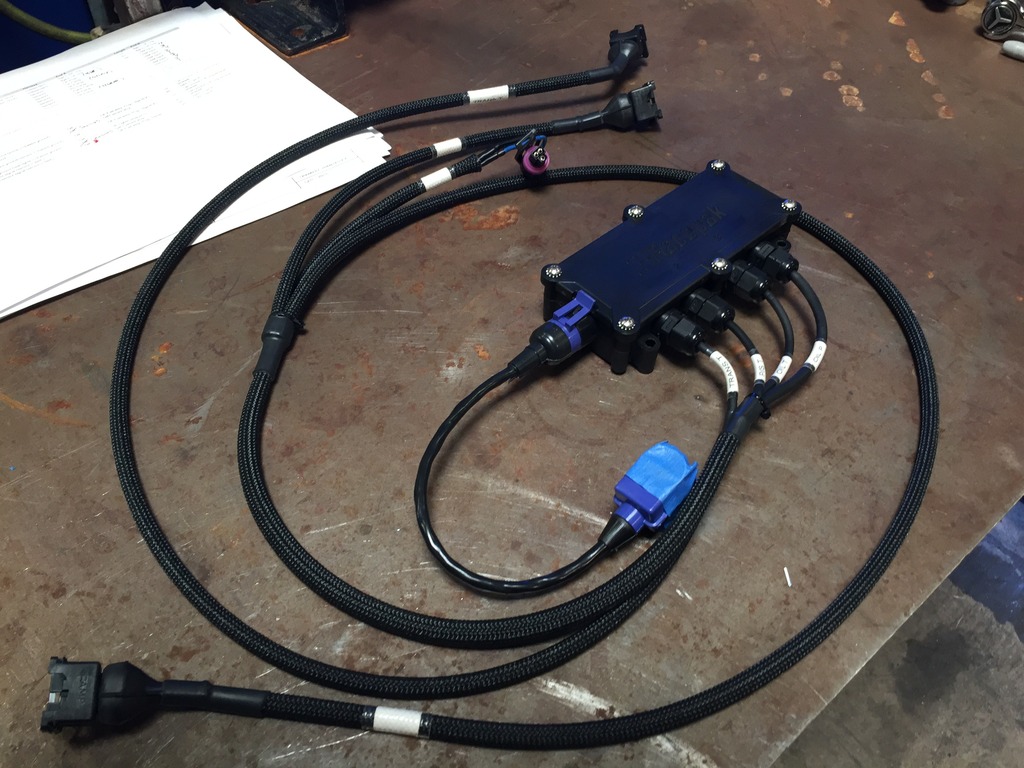
Got the USM (Universal Sensor Module) sorted. The USM is a four channel add-on to the Racepack digital dash allowing the addition of any sensors you want. Black box in the pic below:
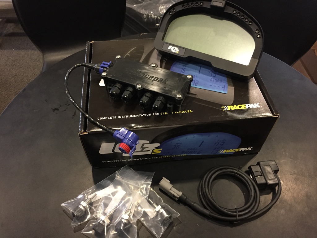
The USM is why I finally took the plunge on a digital display. The original plan had been to add at least two more Accutech SMI gauges to the two I already had in the car so I could keep track of temperatures of all the various important bits. I realized I was heading down a path to having a very busy interior with a lot of things to try to keep an eye on.
The digital dash simplifies everything into one place where I can program warnings for each input and leave the dash to monitor things while I just drive. The dash pulls most of the engine vitals info I need right through the OBDII but the USM makes it possible to add the extra sensors I wanted and simplifies the wiring by transferring everything to the display via one V-net cable.
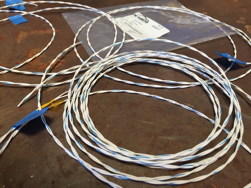
The sensors are already installed in their various locations, documented earlier in this thread. Now, on to wiring up the sensors to the USM. Here I’m using milspec /32 wire same as previously, but this time in 22ga twisted pairs. The twisting is a method of shielding the signal from interference. Frankly, you don't need it for these types of sensor’s signals but here I used it because it helps keep things tidy:
Wiring within the USM box. The USM has a strain relief feature on the inlets which is a nice touch; tighten the outer nut and it clamps down on the wire to secure it in place:
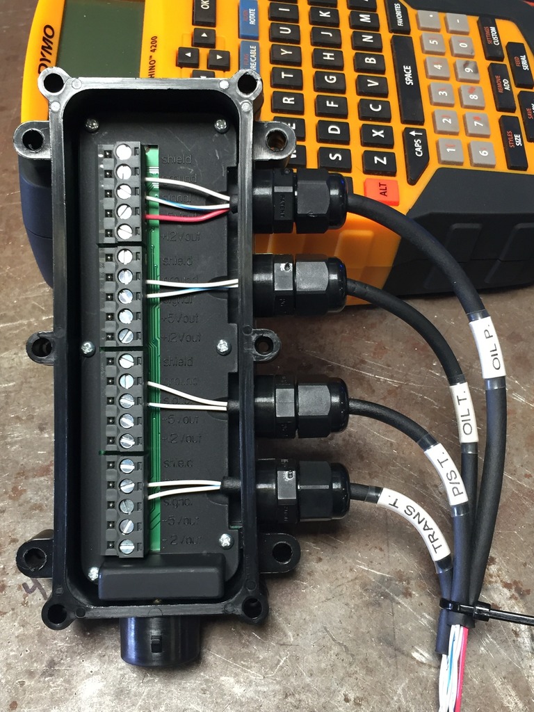
The finished USM harness:
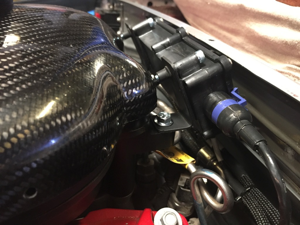
Mounting the box was done on the top/rear of the engine via a pair of simple brackets. Yes it’s tight back there. This is mounted to the engine so that all the sensor wiring can stay with the motor when it’s removed, just disconnect the single V-net cable connector:
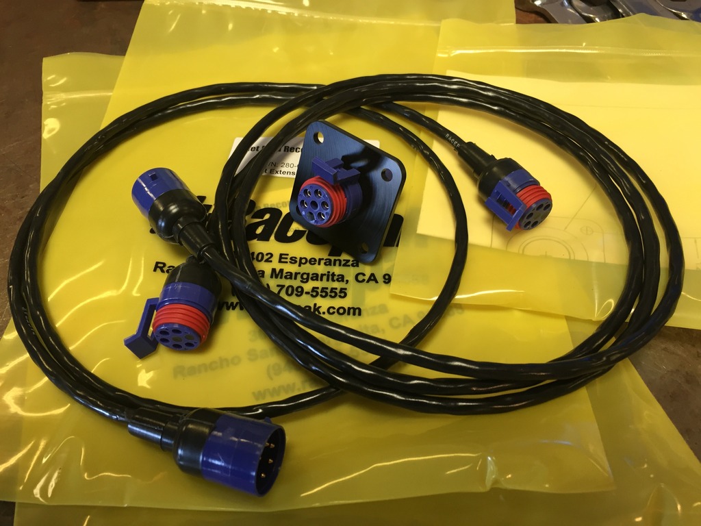
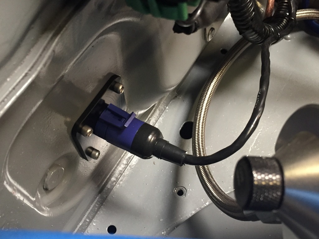
With the box mounted we just need to run the V-net cable to the display. This could be done with one long cable that would need to pass through the firewall, or a bit cleaner version here that involves two shorter cables and a bulkhead connector:
Tidy
The remaining wiring to be done was to tie in where necessary on the GM wiring harness. Most of this was coming through the firewall from the chassis harness - things like ignition switch, start button, lights, fan, drive by wire throttle, OBDII, etc.
I blasted through this and forgot to take all but one picture - V8R advised that the throttle pedal signal is very sensitive to interference, so for this I ran a 6-wire shielded cable on both the chassis and engine side:
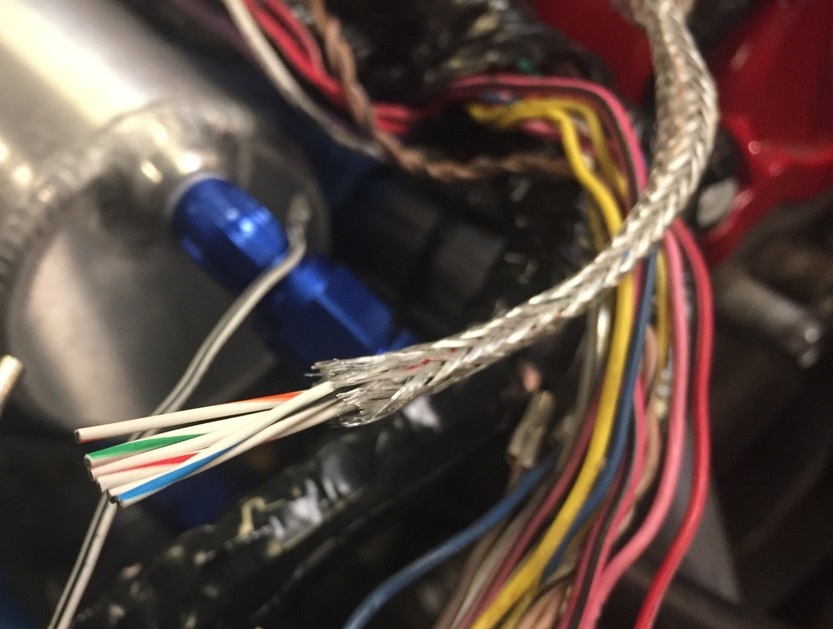
The rest was just patching stuff into the existing engine harness. The stuff I added is all on par with what I did on the chassis side, but I’d love to re-do the entire engine harness in the future so that it is all up to higher standards. However, for now it’s a good working harness and this thing needs to be running!
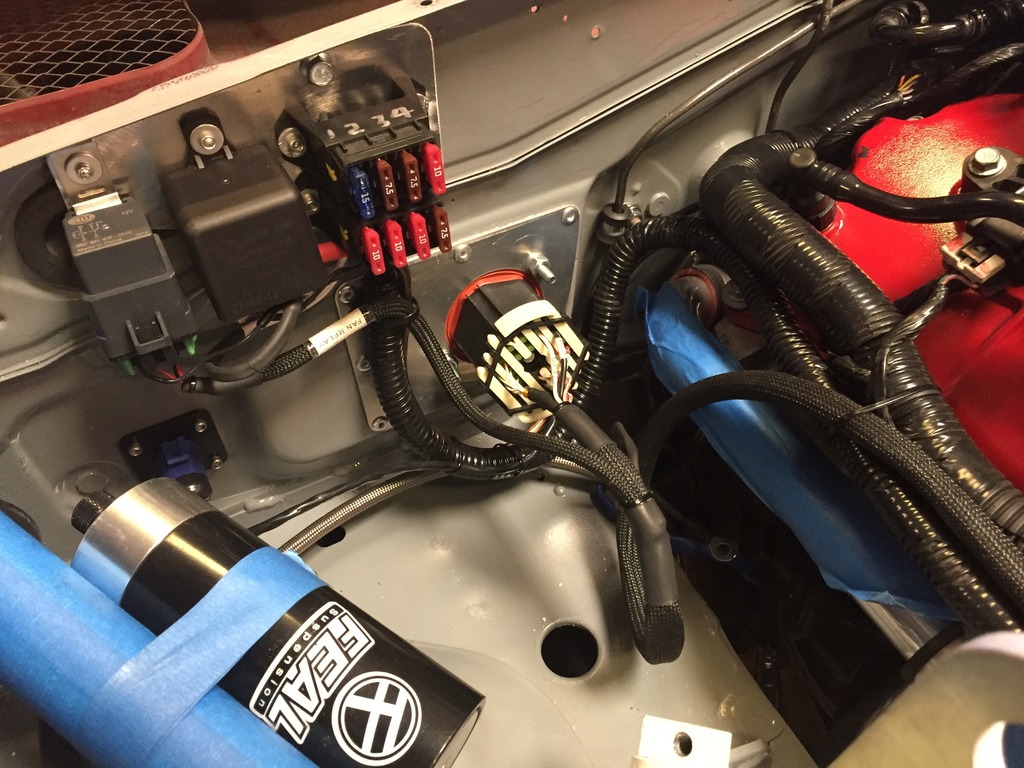
All of the wiring interface from chassis to engine converges in the rear right corner of the engine bay. Everything is set up to disconnect from the chassis quickly/simply and comes out intact with the engine. There’s only four total things to disconnect, all located here: main bulkhead connector, v-net connector, engine ground and one M6 bolt that holds the fuse/relay plate to the firewall. Not trying to hide wires or tuck anything away, the goal here is easily accessible and quickly removable:
The USM is why I finally took the plunge on a digital display. The original plan had been to add at least two more Accutech SMI gauges to the two I already had in the car so I could keep track of temperatures of all the various important bits. I realized I was heading down a path to having a very busy interior with a lot of things to try to keep an eye on.
The digital dash simplifies everything into one place where I can program warnings for each input and leave the dash to monitor things while I just drive. The dash pulls most of the engine vitals info I need right through the OBDII but the USM makes it possible to add the extra sensors I wanted and simplifies the wiring by transferring everything to the display via one V-net cable.
The sensors are already installed in their various locations, documented earlier in this thread. Now, on to wiring up the sensors to the USM. Here I’m using milspec /32 wire same as previously, but this time in 22ga twisted pairs. The twisting is a method of shielding the signal from interference. Frankly, you don't need it for these types of sensor’s signals but here I used it because it helps keep things tidy:
Wiring within the USM box. The USM has a strain relief feature on the inlets which is a nice touch; tighten the outer nut and it clamps down on the wire to secure it in place:
The finished USM harness:
Mounting the box was done on the top/rear of the engine via a pair of simple brackets. Yes it’s tight back there. This is mounted to the engine so that all the sensor wiring can stay with the motor when it’s removed, just disconnect the single V-net cable connector:
With the box mounted we just need to run the V-net cable to the display. This could be done with one long cable that would need to pass through the firewall, or a bit cleaner version here that involves two shorter cables and a bulkhead connector:
Tidy
The remaining wiring to be done was to tie in where necessary on the GM wiring harness. Most of this was coming through the firewall from the chassis harness - things like ignition switch, start button, lights, fan, drive by wire throttle, OBDII, etc.
I blasted through this and forgot to take all but one picture - V8R advised that the throttle pedal signal is very sensitive to interference, so for this I ran a 6-wire shielded cable on both the chassis and engine side:
The rest was just patching stuff into the existing engine harness. The stuff I added is all on par with what I did on the chassis side, but I’d love to re-do the entire engine harness in the future so that it is all up to higher standards. However, for now it’s a good working harness and this thing needs to be running!
All of the wiring interface from chassis to engine converges in the rear right corner of the engine bay. Everything is set up to disconnect from the chassis quickly/simply and comes out intact with the engine. There’s only four total things to disconnect, all located here: main bulkhead connector, v-net connector, engine ground and one M6 bolt that holds the fuse/relay plate to the firewall. Not trying to hide wires or tuck anything away, the goal here is easily accessible and quickly removable:
Reply
2
2
03-28-2017, 08:29 AM
#511
Junior Member

Join Date: Jan 2007
Posts: 230
Total Cats: -23
Yeah, I wish DIYAutoTune would stop hyping them so much. They're big and bulky. But they're better than nothing. I bought a "kit" before I knew what I needed or wanted. With the project car 400 miles away from where I live, I needed to be able to jam for 48 hrs straight when I arrived to work on it. I couldn't afford to wait a few days for the ideal specialty connectors to arrive as that would actually set progress back weeks, if not months. But if I ever get tired of driving the thing and want another project, I'll redo much of it as Ryan has demonstrated here.
Also, dry break connectors for all fluids would be sweet for WRC style pit stops.
Also, dry break connectors for all fluids would be sweet for WRC style pit stops.
Reply
0
0
 03-28-2017, 05:46 PM
#514
Yeah, I wish DIYAutoTune would stop hyping them so much. They're big and bulky. But they're better than nothing. I bought a "kit" before I knew what I needed or wanted. With the project car 400 miles away from where I live, I needed to be able to jam for 48 hrs straight when I arrived to work on it. I couldn't afford to wait a few days for the ideal specialty connectors to arrive as that would actually set progress back weeks, if not months. But if I ever get tired of driving the thing and want another project, I'll redo much of it as Ryan has demonstrated here.
https://www.bmotorsports.com/shop/in.../cPath/109_542
Will have DTM, DT, DTP, with various crimper options, etc up soon. Will also have a 2.3mm bladed series a lot like what you find on the Miata with the Automotive Master Connector Kit CONN-100946 . More to come soon to elevate custom car & projects like the wiring work in this thread.
Reply
0
0
03-30-2017, 02:44 AM
#515
Supporting Vendor
Thread Starter
iTrader: (3)
Join Date: Jul 2006
Location: San Diego
Posts: 3,303
Total Cats: 1,216
Taking a detour for a bit, our tech day at the shop is coming up this Saturday and a couple days ago I realized that April 1 will be the one year mark to the day from when the car rolled in to the shop and the old engine came out. Decided the car should be on the ground and on display out front on that day!
So, the next couple days will be a bit of jumping around with random updates as I prioritize just the things needed to get the car on the ground.
Front Suspension
Clearly we were in need of some suspension to set the car on! Installed the following:
Feal 442 coilovers
Control arms with spherical bearings
Spindles with fresh hubs
R package tie rod ends
V8R upper rebuildable ball joints
Bauer extended lower ball joints

Notes...
- haven't sorted out the front sway bar yet but don't need that for Saturday.
- V8R front upper ball joints are tight until they lap in (takes a couple hundred miles). Correct assembly is to torque top cap down then back it off one "notch" of the lock ring and then install the lock ring. Reset the lash after first track day or 200 miles.
Setting the shock length/bump travel in the front (done with spring removed from the shock assembly):

Driveshaft
Installed the driveshaft with rear subframe and differential. Has to be done together as the Getrag has a long shaft on the flange to the driveshaft that the driveshaft slides over, so you lower the diff about 12 inches, install the driveshaft and then raise the diff with the driveshaft attached.
The CV joint on the driveshaft gave us some trouble, the CV wants to spring apart and has to be held together while installed. During first install something came unseated inside and the bearings locked up. Quickly evident as the drivetrain wouldn't rotate because the CV was locked at one angle. Had to disassemble/reassemble the CV (and order the proper CV grease) and then reinstall. Everything is in and happy now. Forgot to take a pic.
Axles
V8R Stage 2 axles - first off, examining these in person they are very nice pieces.
Comes marked as one long and one short. Long one goes on the right side. The CV joints in these are packed with grease and the grease can keep the CVs from compressing fully so at first it appeared the axles were too long. Pulled them out and worked the joints around while putting body weight on them and they shortened up a lot and then installed fine.
Current state of affairs in the rear:

So, axles, hubs and spindles are in along with the V8R upper pro series control arms. What's NOT in are my lower control arms complete with spherical bearings. The placeholders right now are factory arms with rubber bushings that were laying around.
This spherical bearing kit had some dimensional issues in some of the rear pieces. Unfortunately the company who makes the bearing kit has been working at a snail's pace to make the necessary changes. As this kit is here for evaluation, this makes it hard to recommend it, but hopefully that stuff will get sorted out soon. As a last resort I can have the existing pieces machined to work right myself, but they assure me they're working on corrected pieces. We'll see, but for the moment these loaner rear lower arms will get the car on the ground.
Ran into one more hurdle in the rear. The beefy axles are larger in just about every dimension than stock Miata axles. Where the axles passes by the coilover, it's very tight. There's juuuuust enough clearance from the CV boot to the lower cup on the rear coilover, so that is OK but the lower lock ring on the coilover has a larger OD than the cup below it and that ring hits the boot:

Can't have these two bits contacting with the axle spinning of course. I believe I have a solution figured out, Feal is sending over some parts that I think I can modify to make a custom low-profile lock ring out of. That stuff arrives Friday.
Fluids
Final thing tonight was getting fluid in the trans and diff since we'll be rolling the car around.
Trans is 75W90
Diff is 75W90 + 4oz Limited Slip Additive. Sounds like snake oil to me but OK we'll follow the spec.
So, the next couple days will be a bit of jumping around with random updates as I prioritize just the things needed to get the car on the ground.
Front Suspension
Clearly we were in need of some suspension to set the car on! Installed the following:
Feal 442 coilovers
Control arms with spherical bearings
Spindles with fresh hubs
R package tie rod ends
V8R upper rebuildable ball joints
Bauer extended lower ball joints
Notes...
- haven't sorted out the front sway bar yet but don't need that for Saturday.
- V8R front upper ball joints are tight until they lap in (takes a couple hundred miles). Correct assembly is to torque top cap down then back it off one "notch" of the lock ring and then install the lock ring. Reset the lash after first track day or 200 miles.
Setting the shock length/bump travel in the front (done with spring removed from the shock assembly):
Driveshaft
Installed the driveshaft with rear subframe and differential. Has to be done together as the Getrag has a long shaft on the flange to the driveshaft that the driveshaft slides over, so you lower the diff about 12 inches, install the driveshaft and then raise the diff with the driveshaft attached.
The CV joint on the driveshaft gave us some trouble, the CV wants to spring apart and has to be held together while installed. During first install something came unseated inside and the bearings locked up. Quickly evident as the drivetrain wouldn't rotate because the CV was locked at one angle. Had to disassemble/reassemble the CV (and order the proper CV grease) and then reinstall. Everything is in and happy now. Forgot to take a pic.
Axles
V8R Stage 2 axles - first off, examining these in person they are very nice pieces.
Comes marked as one long and one short. Long one goes on the right side. The CV joints in these are packed with grease and the grease can keep the CVs from compressing fully so at first it appeared the axles were too long. Pulled them out and worked the joints around while putting body weight on them and they shortened up a lot and then installed fine.
Current state of affairs in the rear:
So, axles, hubs and spindles are in along with the V8R upper pro series control arms. What's NOT in are my lower control arms complete with spherical bearings. The placeholders right now are factory arms with rubber bushings that were laying around.
This spherical bearing kit had some dimensional issues in some of the rear pieces. Unfortunately the company who makes the bearing kit has been working at a snail's pace to make the necessary changes. As this kit is here for evaluation, this makes it hard to recommend it, but hopefully that stuff will get sorted out soon. As a last resort I can have the existing pieces machined to work right myself, but they assure me they're working on corrected pieces. We'll see, but for the moment these loaner rear lower arms will get the car on the ground.
Ran into one more hurdle in the rear. The beefy axles are larger in just about every dimension than stock Miata axles. Where the axles passes by the coilover, it's very tight. There's juuuuust enough clearance from the CV boot to the lower cup on the rear coilover, so that is OK but the lower lock ring on the coilover has a larger OD than the cup below it and that ring hits the boot:
Can't have these two bits contacting with the axle spinning of course. I believe I have a solution figured out, Feal is sending over some parts that I think I can modify to make a custom low-profile lock ring out of. That stuff arrives Friday.
Fluids
Final thing tonight was getting fluid in the trans and diff since we'll be rolling the car around.
Trans is 75W90
Diff is 75W90 + 4oz Limited Slip Additive. Sounds like snake oil to me
but OK we'll follow the spec.
Last edited by ThePass; 07-13-2017 at 01:31 PM.
Reply
1
1
 03-30-2017, 10:14 AM
#518
Elite Member

Join Date: Sep 2015
Location: Seattle, WA
Posts: 1,651
Total Cats: 884
I asked Shandelle about that locating pin on the diff and he said I'd be fine cutting off some from it. I can't remember how much I cut off, it's somewhere buried in my thread but it was a pretty small amount. Definitely makes the driveshaft easier to install.
Reply
0
0
03-30-2017, 12:00 PM
#520
Supporting Vendor
Thread Starter
iTrader: (3)
Join Date: Jul 2006
Location: San Diego
Posts: 3,303
Total Cats: 1,216
Yep^ Aidan's got it. The lower lock ring in that pic isn't yet locked down on to the bottom mount but is already touching the boot. I should have a solution figured out, parts arrive Friday to give it a go.
Reply
0
0


