
Does this MS3 look right?


Thread Starter
Junior Member
Joined: Oct 2008
Posts: 113
Total Cats: 5
From: Cortland, Ohio
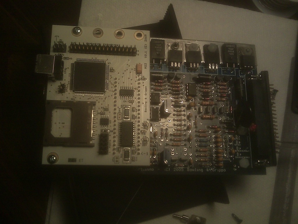
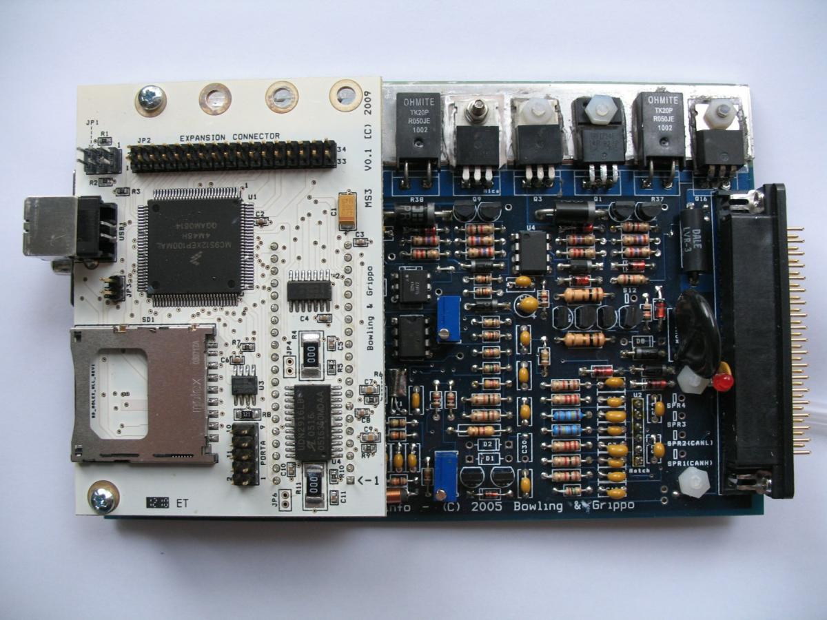
We're about done. Anyone see anything that looks wrong? I realize the photos suck, they are from my crappy phone.
Front:
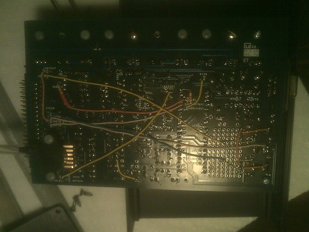
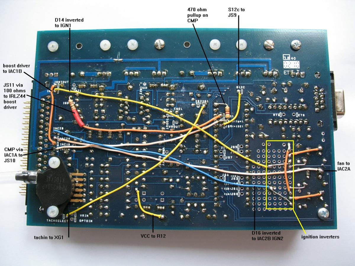
Here's the back side:
Front:
Here's the back side:
Reply
 0
0

0
Supporting Vendor

Joined: Sep 2006
Posts: 2,332
Total Cats: 67
Er, yeah, you should have used better lighting instead of resorting to the flash.
As for the ECU itself, nothing wrong jumps out at me.
As for the ECU itself, nothing wrong jumps out at me.
Reply
0
0

I'm curious what's going on with your ignition outputs.
What kind of car is this for, a Miata or something like a fwd BP (distributor ignition)?
What kind of car is this for, a Miata or something like a fwd BP (distributor ignition)?

Reply
0
0

looks like it would work for a miata, but the ignition ouputs look wrong.
Looks like a combo of Joe's spark output mod (possible incorrectly done) and a BIP output on one of the channels.
Looks like a combo of Joe's spark output mod (possible incorrectly done) and a BIP output on one of the channels.
Reply
0
0
Thread Starter
Junior Member
Joined: Oct 2008
Posts: 113
Total Cats: 5
From: Cortland, Ohio
This is for a turbocharged Miata motor in a Lotus 7. The build is in the Build Log section.
I am still confused about the ignition wiring. Some MS3 and MS2 builds have them crossed, while others do not. I've been told to cross them and not to, but I haven't been given an explaination why. So far, the oscilloscope hasn't shown any signs of the Jimstim operating out of order... I will try to get some better pictures.
I am still confused about the ignition wiring. Some MS3 and MS2 builds have them crossed, while others do not. I've been told to cross them and not to, but I haven't been given an explaination why. So far, the oscilloscope hasn't shown any signs of the Jimstim operating out of order... I will try to get some better pictures.
Reply
0
0
Ignition output wiring seems very wrong. What coils? Wasted spark or COP? What's going on with the BIP? What is JS11 doing?
Reply
0
0

Newb
Joined: Nov 2011
Posts: 6
Total Cats: 1
From: Chardon, OH
I (Nathan's dad) built the MS board pictured above. Nathan built the rest of the Lotus 7 starting with a load of steel tubing, a scrap Miata from the police impound lot, and a welder. The Lotus has a '94 1.8L Miata engine in it. Right now the engine is pretty much stock, except for the turbo. The engine runs fine with the stock ECU, and the turbo isn't doing anything at the moment. The next thing we will try is to get the engine running with the Megasquirt using the stock coils and injectors.
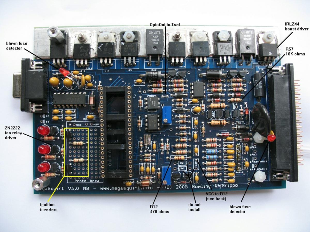
I built the board according to the megamanual, then modified it using the Megasquirt 2 assembly instructions at miataturbo.wikidot.com. CMP comes in on JS10, CKP on XG1, and OptoIn is connected to VCC. I put the boost control FET at Q16, driven by JS11, and it's output is wired to IAC1B. Q7 was replaced with a 2N2222 and is wired to IAC2A for fan control. We used Joe Perez's ignition inverters driven by the D14 and D16 drivers. The board talks to TunerStudio and has been tested with a JimStim and a scope. I am now in the process of designing the wiring harness modifications prior to installing the Megasquirt in the car. This will be a standalone installation.
I became confused when some instructions showed the ignition signals crossed and others not crossed. I decided to not cross the ignition, so D14 inverted goes to IGN which will drive coils 1&4, and D16 inverted goes to IAC2B which will drive coils 2&3. Assuming the falling edge of CKP that occurs during CMP high indicates cylinder 1 TDC, then we appear to be getting the correct firing pulses.
When I started to consider the various injector wiring diagrams I could find on the web, seeing INJ1 driving injectors 1&3 and INJ2 driving 2&4 initially appeared to be an error. I even found one harness drawing that shows INJ1 driving 2&3 and INJ2 driving 1&4, same grouping as the ignition. I spent several evenings trying to figure out what the MS is doing with the injectors, and why. It appears that the default setup (batch injection) is to fire each bank once per cycle, not necessarily synchronized to anything, which reminds me of the CIS injection on my '74 Audi Fox. In this case it may not make a lot of difference how the injectors are wired up.
I'm still experimenting with the JimStim and the scope. I tried setting the MS up to do semi-sequential injection. What it appears to be doing now is firing injectors 2&4 during the exhaust stroke of 1, and injectors 1&3 during the compression stroke of 1. Here is a drawing (using Excel) of what I'm seeing on the scope:
Here is the same data as a polar plot. Each quadrant of the circle is one stroke. The upper right quadrant is the power stroke of cylinder 1.
Here is a chart of what is happening in each cylinder on each stroke. Red is when the injector is squirting, orange is the fuel just sitting around in the manifold, yellow is when the intake value is open and the fuel is pulled into the cylinder. Red and yellow stripes is when the injector is squirting into an open intake. Asterisk indicates plug firing.
This is with the engine loafing at 1500 RPM, BTW. I realize the squirts will get longer (start earlier?) at higher loads.
if I swap the injector wires, then injectors 1&3 squirt during the exhaust stroke of 1, and injectors 2&4 during the compression stroke of 1, and I get this sequence:
This setup seems more symmetrical. Whether it is better, I can't say. From what I've read, the engine will run either way, and we can experiment and see if one arrangement works better. Maybe we should use barrel connectors in the injector wires so we can swap them more easily.
One thing we would like to find is a plain vanilla msq file for an unmodified Miata engine. We have an MS3 CPU daughterboard, and most of the example msq files we found are for earlier boards and can't be loaded into the MS3. The only example I could find that would load into our board was for a modified engine, and I'm not sure how appropriate it is for a stock engine.
Last edited by engdahl; Dec 28, 2011 at 03:31 AM.
Reply
1
1
Newb
Joined: Nov 2011
Posts: 6
Total Cats: 1
From: Chardon, OH
And here is the preliminary list of connections to the car:
Since a Lotus 7 does not have AC, remote mirrors, heated windows, (or windows for that matter), the Miata harness has already been greatly reduced.
Code:
37 pin							harness
conn	ECU	MS	description			color
======	===	======	============================	==========
1		gnd
2		gnd
3		spr1	spare
4		spr2	spare
5		spr3	spare
6		spr4	spare
7	2A	gnd	engine ground			blk
8	2A	gnd	engine ground			blk
9	2A	gnd	engine ground			blk
10	2C	gnd	O2 ground			blk/lt grn
11	2D	gnd	sensor ground			blk/blu
12		gnd
13		gnd
14		gnd
15		gnd
16		gnd
17	2B	gnd	engine ground			blk
18	2B	gnd	engine ground			blk
19	2B	gnd	engine ground			blk
20	2P	mat	intake air temperature		(new wire)
21	2Q	clt	coolant temperature		blu/wht
22	2M	tps	throttle position sensor	red/blk
23	2N	O2	oxygen sensor			red/blu
24	2E	tachin	tach, crank angle sensor CKP	wht
25	2G	iac1a	crank angle CMP (TDC index)	yel/blu
26		vref	+5 reference for sensors	(not used)
27		iac1b	turbo boost control		(new wire)
28	1B	12 raw	12 volts from main relay	wht/red
29	1L	iac2a	fan relay			blk/grn
30		idl	idle air control		(not used)
31	1H	iac2b	ignition coils 2&3		brn
32	2U	inj1	injector 1			yel
33	2Y	inj1	injector 3			grn/wht
34	2Z	inj2	injector 4			grn
35	2V	inj2	injector 2			yel/blk
36	1G	ign	ignition coils 1&4		brn/yel
37	2T	fp1	fuel pump relay			lt grn
Reply
0
0
Newb
Joined: Nov 2011
Posts: 6
Total Cats: 1
From: Chardon, OH
Here is how I installed the boost control, somewhat following the Miata MS2 mods page at http://miataturbo.wikidot.com/ms2-m, but using more of the preexisting parts and wiring on the board.

I have one question regarding the boost control: should the 1N4002 catch diode get mounted on the solenoid, as implied by the schematic, or should it be mounted on the megasquirt, as shown here: http://boostedmiata.com/MS/built/lea...e/CIMG1761.jpg? I noticed from the datasheet that the IRLZ44 already has a built-in catch diode.
I have one question regarding the boost control: should the 1N4002 catch diode get mounted on the solenoid, as implied by the schematic, or should it be mounted on the megasquirt, as shown here: http://boostedmiata.com/MS/built/lea...e/CIMG1761.jpg? I noticed from the datasheet that the IRLZ44 already has a built-in catch diode.
Reply
0
0
Newb
Joined: Nov 2011
Posts: 6
Total Cats: 1
From: Chardon, OH
Insecurity, I guess. *I* think I know what I'm doing, but Nathan wanted a second opinion before the smoke test. I'm very slow and methodical about things like this -- I've been mumbling on the harness for maybe 3-4 weeks now in my spare time. Nathan wants to get rolling. However, I think we're finally ready to start snipping the harness.
Reply
0
0
Here is how I installed the boost control, somewhat following the Miata MS2 mods page at http://miataturbo.wikidot.com/ms2-m, but using more of the preexisting parts and wiring on the board.
I have one question regarding the boost control: should the 1N4002 catch diode get mounted on the solenoid, as implied by the schematic, or should it be mounted on the megasquirt, as shown here: http://boostedmiata.com/MS/built/lea...e/CIMG1761.jpg? I noticed from the datasheet that the IRLZ44 already has a built-in catch diode.
I have one question regarding the boost control: should the 1N4002 catch diode get mounted on the solenoid, as implied by the schematic, or should it be mounted on the megasquirt, as shown here: http://boostedmiata.com/MS/built/lea...e/CIMG1761.jpg? I noticed from the datasheet that the IRLZ44 already has a built-in catch diode.
We've found that the boost control extra flyback diode is not required--there is no harm to adding it, but we've seen no benefit/detriment either way.
Reply
0
0


Thread
Thread Starter
Forum
Replies
Last Post
Zaphod
MEGAsquirt
47
Oct 26, 2018 11:00 PM


