MEGAsquirt A place to collectively sort out this megasquirt gizmo

Finally got a MS, have wiring questions

Thread Tools
 
Search this Thread
 
Old 09-02-2008, 06:02 PM
  #1  
Slowest Progress Ever
Thread Starter
iTrader: (26)
 
thirdgen's Avatar
 
Join Date: Oct 2007
Location: The coal ridden hills of Pennsylvania
Posts: 6,022
Total Cats: 304
Default Finally got a MS, have wiring questions

So I bought an MS 1 with a 3.0 that was off of a running a 97 miata, but I have some wiring issues. The car it came off of was using a parallel setup, which is the way I will be using it. I had a boomslang harness made for my 99 and the wires are as follows...
1) 12V
2) IAT
3) Knock
4) Gnd
5) Coil 2
6) Injs 2&4
7) CLT
8) Gnd
9) TPS
10) Coil 1
11) Injs 1&3

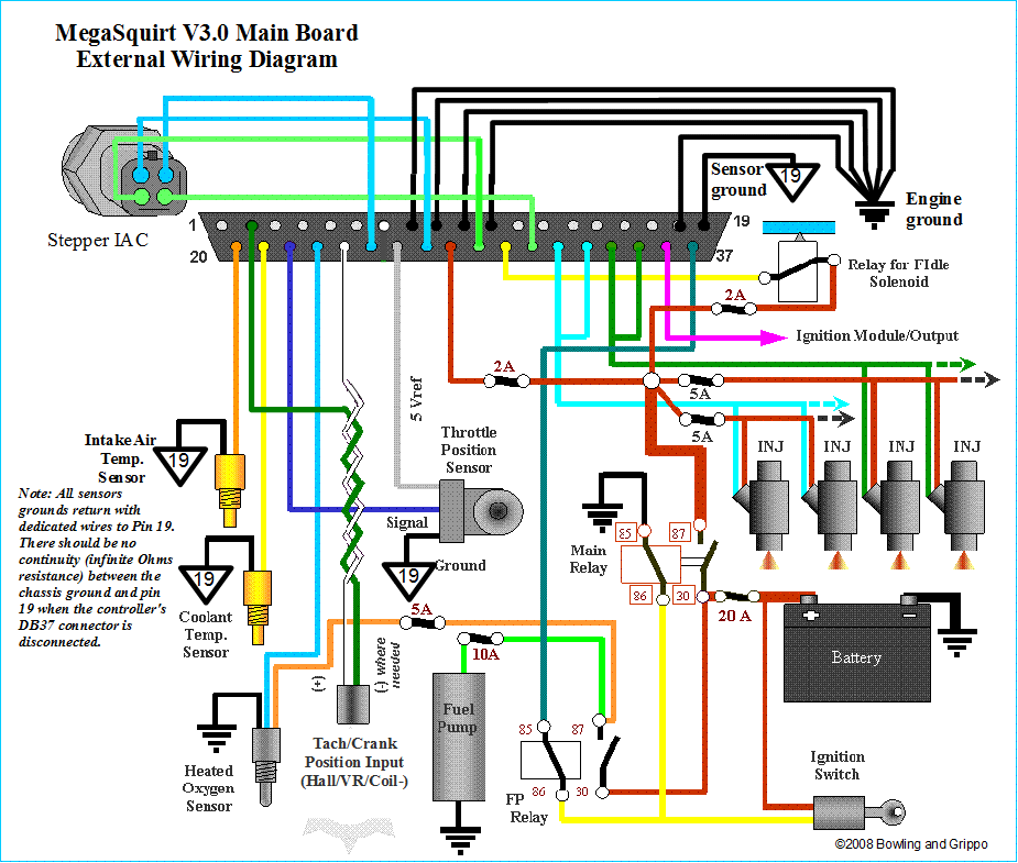
I read the wiring diagram for the DB 37, and am confused a bit as to what goes where. I have DB37 pin 20 to my IAT, pin 21 to my CLT, Pins 32 & 34 to my injs, but as far as my grounds and my coils...what pins to I wire these to? I am going to install a NA CAS, what pins do those wires go to? The NA CAS has 4 wires coming from it...if I'm not mistaken, 2 should go to MS, 1 is a 12V, and the other is a Gnd. Where can I get this sensor, preferably with a pigtail?
thirdgen is offline  
Old 09-02-2008, 06:03 PM
  #2  
Slowest Progress Ever
Thread Starter
iTrader: (26)
 
thirdgen's Avatar
 
Join Date: Oct 2007
Location: The coal ridden hills of Pennsylvania
Posts: 6,022
Total Cats: 304
Default

Forgot...Brown analog wire from my LC-1 is on DB37 pin 23, correct?
thirdgen is offline  
Old 09-02-2008, 06:28 PM
  #3  
Elite Member
iTrader: (16)
 
patsmx5's Avatar
 
Join Date: Aug 2007
Location: Houston, TX
Posts: 9,297
Total Cats: 477
Default


Last edited by patsmx5; 09-02-2008 at 06:47 PM.
patsmx5 is offline  
Old 09-02-2008, 06:30 PM
  #4  
Elite Member
iTrader: (21)
 
paul's Avatar
 
Join Date: Jun 2006
Location: Point Pleasant, NJ
Posts: 2,957
Total Cats: 2
Default

that's an awesome image.
paul is offline  
Old 09-02-2008, 07:32 PM
  #5  
Slowest Progress Ever
Thread Starter
iTrader: (26)
 
thirdgen's Avatar
 
Join Date: Oct 2007
Location: The coal ridden hills of Pennsylvania
Posts: 6,022
Total Cats: 304
Default

That is an awesome image...so on my boomslang, there are 2 injector wires. 1 for 1&3 and 1 for 2&4. I spliced them with DB37 pins 32 and 34. So the 12v from 1B on my factory harness goes to DB37 pin 28? What pin or pins on DB37 do I splice my coil wires to?
thirdgen is offline  
Old 09-02-2008, 07:37 PM
  #6  
Elite Member
iTrader: (16)
 
patsmx5's Avatar
 
Join Date: Aug 2007
Location: Houston, TX
Posts: 9,297
Total Cats: 477
Default

See on the second image where it says "COILS"? One says "COILS 31" and the other "COILS 36" the number is the number to hook to on the DB 37. So coils go to DB 31 and DB36.
patsmx5 is offline  
Old 09-02-2008, 07:39 PM
  #7  
Boost Pope
iTrader: (8)
 
Joe Perez's Avatar
 
Join Date: Sep 2005
Location: Chicago. (The less-murder part.)
Posts: 33,027
Total Cats: 6,593
Default

Originally Posted by thirdgen
I read the wiring diagram for the DB 37, and am confused a bit as to what goes where. I have DB37 pin 20 to my IAT, pin 21 to my CLT, Pins 32 & 34 to my injs, but as far as my grounds and my coils...what pins to I wire these to?
You should split the big heavy wires you're using for your injector lines and bridge them across two pins each, such that 32/33 are bridged, and 34/35 are bridged. Or just use four wires, one per injector per pin.

Grounds... Pin 2 and pins 7 through 19 are all grounds. Pick five or six of 'em and run heavy ground wires to them. Connect a couple of them to your boomslang grounds (3A, 3B, 3C) and run the others direct to the head. You don't have to connect every single ground pin, but you can never be too well grounded.

Coils... This actually changes depending on how whoever built your MS wired the spark output drivers. The "officially sanctioned" method is for SparkA to hit pin 36, and SparkB to hit pin 31. If you use an NA CAS, and set up your wheel config as DIY suggests, your spark outputs will be "backwards" (relative to common logic) so SparkA will drive coils 2&3, and SparkB will drive 1&4.

I am going to install a NA CAS, what pins do those wires go to? The NA CAS has 4 wires coming from it...if I'm not mistaken, 2 should go to MS, 1 is a 12V, and the other is a Gnd.
Yup.

Like SparkOut, CAS in pinout varies with whoever built it. The usual standard is CKP at pin 24(Techin), and CMP at pin25 (IAC1A).

Wire color at the CAS pigtail:
W/R = +12
B/LG = GND
W = CKP
Y/L = CMP

Where can I get this sensor, preferably with a pigtail?
From an NA. Or from the large pile of them that is no doubt building up at the entrance to the seventh level of hell.

Originally Posted by thirdgen
Forgot...Brown analog wire from my LC-1 is on DB37 pin 23, correct?
Yup.
Joe Perez is offline  
Old 09-03-2008, 07:59 AM
  #8  
Slowest Progress Ever
Thread Starter
iTrader: (26)
 
thirdgen's Avatar
 
Join Date: Oct 2007
Location: The coal ridden hills of Pennsylvania
Posts: 6,022
Total Cats: 304
Default

So I finished splicing my DB37 to my boomslang except for 1 wire, the knock sensor wire. Does that go anywhere from my Boomslang to the DB37? I have 6 wires left on my DB37...pin 24 and pin 25 which are for my CAS, pin 23 which is for my LC-1's brown analog wire, pin 27, pin 29, and pin 37. Where do those last 3 go?
thirdgen is offline  
Old 09-03-2008, 10:43 AM
  #9  
Elite Member
iTrader: (16)
 
patsmx5's Avatar
 
Join Date: Aug 2007
Location: Houston, TX
Posts: 9,297
Total Cats: 477
Default

Originally Posted by thirdgen
So I finished splicing my DB37 to my boomslang except for 1 wire, the knock sensor wire. Does that go anywhere from my Boomslang to the DB37? I have 6 wires left on my DB37...pin 24 and pin 25 which are for my CAS, pin 23 which is for my LC-1's brown analog wire, pin 27, pin 29, and pin 37. Where do those last 3 go?
If you are keeping the stock ECU don't hook up DB 27, 29, or 37. 27 and 29 are for idle control, and 37 is for fuel pump relay. Note all I'm doing is looking at the wiring diagrams I posted to answer all your questions.
patsmx5 is offline  
Old 09-03-2008, 01:12 PM
  #10  
Slowest Progress Ever
Thread Starter
iTrader: (26)
 
thirdgen's Avatar
 
Join Date: Oct 2007
Location: The coal ridden hills of Pennsylvania
Posts: 6,022
Total Cats: 304
Default

So aside from the CAS...that looks like it. Thanks for your help guys.
thirdgen is offline  
Old 09-03-2008, 06:22 PM
  #11  
Boost Pope
iTrader: (8)
 
Joe Perez's Avatar
 
Join Date: Sep 2005
Location: Chicago. (The less-murder part.)
Posts: 33,027
Total Cats: 6,593
Default

Originally Posted by thirdgen
So I finished splicing my DB37 to my boomslang except for 1 wire, the knock sensor wire. Does that go anywhere from my Boomslang to the DB37?
The MS is capable of knock detection, however it requires both an internal mod and an external filter/amplifier such as KnockSenseMS. So if you do not have both of these things, then the knock sensor is not connected to the MS.

pin 27, pin 29, and pin 37. Where do those last 3 go?
To clarify 27 and 29, like 25 and 31, are general-purpose pins. Although they are labeled IAC, they are actually not connected to anything internally and are usually used for mods. An example of this is the fact that you have the CMP input mod connected to IAC1A, at pin 25.

37, as Pats' said, is a dedicated FP wire which you will not use.
Joe Perez is offline  
Old 09-28-2008, 03:09 PM
  #12  
Elite Member
iTrader: (6)
 
kenzo42's Avatar
 
Join Date: Sep 2007
Location: CA
Posts: 2,016
Total Cats: 13
Default

Originally Posted by Joe Perez
Pin 37, as Pats' said, is a dedicated FP wire which you will not use.
What triggers the fuel pump if you don't have pin 37 connected and NO AFM present? 91 parallel DIY install, btw.

Or does the above quoted text only apply to PNP?
kenzo42 is offline  
Old 09-29-2008, 12:20 PM
  #13  
Supporting Vendor
 
Matt Cramer's Avatar
 
Join Date: Sep 2006
Posts: 2,332
Total Cats: 67
Default

Originally Posted by kenzo42
What triggers the fuel pump if you don't have pin 37 connected and NO AFM present? 91 parallel DIY install, btw.
Absolutely nothing - you must have one or the other connected.

Or does the above quoted text only apply to PNP?
The PNP has a different fuel pump control circuit. Pin 37 is internally connected to a circuit that takes over part of the starting circuit to drive the fuel pump relay.
__________________
Matt Cramer
www.diyautotune.com
Matt Cramer is offline  
Old 09-29-2008, 12:23 PM
  #14  
Boost Czar
iTrader: (62)
 
Braineack's Avatar
 
Join Date: May 2005
Location: Chantilly, VA
Posts: 79,494
Total Cats: 4,080
Default

Originally Posted by Matt Cramer
Absolutely nothing - you must have one or the other connected.

unless you jump FP and GND in the diagnostics box like us lazy folk.
Braineack is offline  
Related Topics
Thread
Thread Starter
Forum
Replies
Last Post
nick470
MEGAsquirt
7
06-16-2017 01:53 PM
slomiata
MEGAsquirt
5
10-07-2015 01:11 PM
zephyrusaurai
Meet and Greet
2
09-28-2015 10:59 PM
btabor
ECUs and Tuning
10
09-28-2015 05:33 PM


Quick Reply: Finally got a MS, have wiring questions


All times are GMT -4. The time now is 04:09 PM.