Notices
MEGAsquirt A place to collectively sort out this megasquirt gizmo

Finally got a MS3x

Old Oct 4, 2014 | 05:27 PM
  #21  
aidandj's Avatar
SADFab Destructive Testing Engineer
iTrader: (5)
 
Joined: Apr 2014
Posts: 18,643
Total Cats: 1,870
From: Beaverton, USA
Default

Should be plugged into your car but with the MS3 unplugged. Like the picture below the step.
Old Oct 4, 2014 | 05:31 PM
  #22  
whinin's Avatar
Thread Starter
Junior Member
 
Joined: Apr 2013
Posts: 359
Total Cats: -4
From: Elgin, SC
Default

I could but I don't have any way to power it off the car.

I bought it 2nd hand from https://www.miataturbo.net/miata-par...9/#post1169300
Old Oct 4, 2014 | 05:33 PM
  #23  
aidandj's Avatar
SADFab Destructive Testing Engineer
iTrader: (5)
 
Joined: Apr 2014
Posts: 18,643
Total Cats: 1,870
From: Beaverton, USA
Default

Originally Posted by whinin
I could but I don't have any way to power it off the car.

I bought it 2nd hand from https://www.miataturbo.net/miata-par...9/#post1169300
That test will tell you if the MS3 card is getting power or if there is a short somewhere. After that there are some tests to test the serial output.
Old Oct 4, 2014 | 05:35 PM
  #24  
whinin's Avatar
Thread Starter
Junior Member
 
Joined: Apr 2013
Posts: 359
Total Cats: -4
From: Elgin, SC
Default

Do I have to pull the board off or just leave it unhooked?
Old Oct 4, 2014 | 05:36 PM
  #25  
aidandj's Avatar
SADFab Destructive Testing Engineer
iTrader: (5)
 
Joined: Apr 2014
Posts: 18,643
Total Cats: 1,870
From: Beaverton, USA
Default

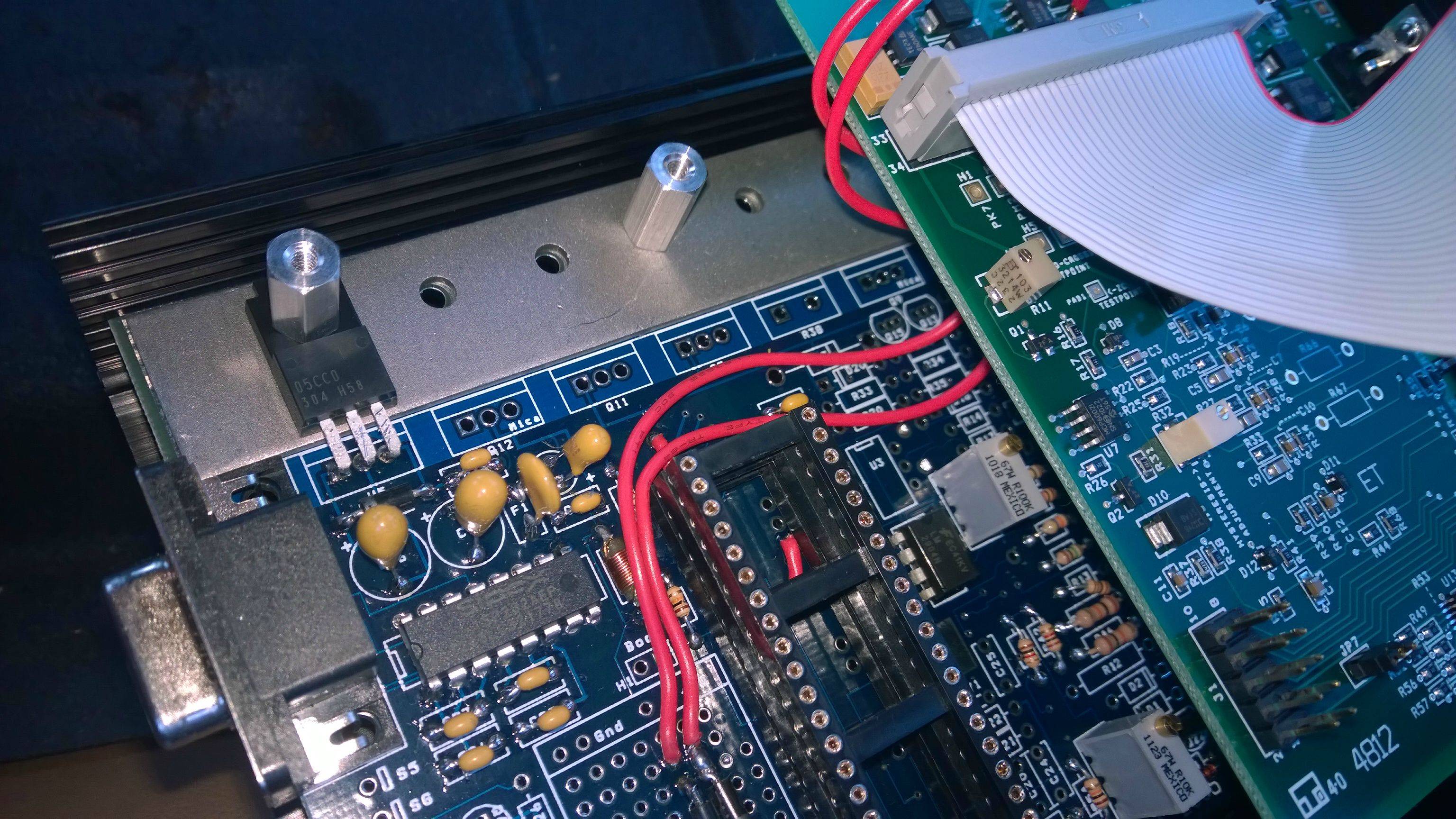
You have to disconnect the MS3 (white board) from the main board. Its a 40 pin connector. You pull it off and then test the pins listed in the guide.

Like this:
http://www.msextra.com/doc/general/pix/dip40voltages.png
Old Oct 4, 2014 | 05:39 PM
  #26  
whinin's Avatar
Thread Starter
Junior Member
 
Joined: Apr 2013
Posts: 359
Total Cats: -4
From: Elgin, SC
Default

10-4.

Give me a few, eating dinner atm. Will report back in about 20m.

Thanks for the help so far man.
Old Oct 4, 2014 | 05:40 PM
  #27  
aidandj's Avatar
SADFab Destructive Testing Engineer
iTrader: (5)
 
Joined: Apr 2014
Posts: 18,643
Total Cats: 1,870
From: Beaverton, USA
Default

No worries I had the same stuff with mine I built. Looks like braineack built it, hopefully he will pop in and help out.
Old Oct 4, 2014 | 06:17 PM
  #28  
whinin's Avatar
Thread Starter
Junior Member
 
Joined: Apr 2013
Posts: 359
Total Cats: -4
From: Elgin, SC
Default

12 volt power coming from the factory harness has 12.34v but at the MS3x there is nothing.
Old Oct 4, 2014 | 06:20 PM
  #29  
whinin's Avatar
Thread Starter
Junior Member
 
Joined: Apr 2013
Posts: 359
Total Cats: -4
From: Elgin, SC
Default

Was I supposed to test those 0v and 5v ones right next to each other? It said 32 and 20 which is what I did. Also on the proto area and the u5 pin and nothing either.
Old Oct 4, 2014 | 06:21 PM
  #30  
aidandj's Avatar
SADFab Destructive Testing Engineer
iTrader: (5)
 
Joined: Apr 2014
Posts: 18,643
Total Cats: 1,870
From: Beaverton, USA
Default

Test the voltage between the right leg of u5 and the center leg of u5.
Old Oct 4, 2014 | 06:33 PM
  #31  
whinin's Avatar
Thread Starter
Junior Member
 
Joined: Apr 2013
Posts: 359
Total Cats: -4
From: Elgin, SC
Default

0.00

But between the left and center there is .50 and it tapers off to 0.00 so long as I keep the leads touched there. If I take the leads off it halts at whatever voltage until I touch the leads back to the legs.

Come to think of it maybe I have the settings a click to far on the multimeter and it is 5 volts between the left and center leg.
Old Oct 4, 2014 | 06:48 PM
  #32  
whinin's Avatar
Thread Starter
Junior Member
 
Joined: Apr 2013
Posts: 359
Total Cats: -4
From: Elgin, SC
Default

Might be a problem.

Name:  fhxVZdr.jpg
Views: 55
Size:  738.1 KB

Am I supposed to have those q12 etc etc chips?
Old Oct 4, 2014 | 06:51 PM
  #33  
aidandj's Avatar
SADFab Destructive Testing Engineer
iTrader: (5)
 
Joined: Apr 2014
Posts: 18,643
Total Cats: 1,870
From: Beaverton, USA
Default

There should be 12 volts between right and center, 5 between left and center. Fiddle with the settings and see if you can get that. Let me know what you find.
Old Oct 4, 2014 | 06:52 PM
  #34  
aidandj's Avatar
SADFab Destructive Testing Engineer
iTrader: (5)
 
Joined: Apr 2014
Posts: 18,643
Total Cats: 1,870
From: Beaverton, USA
Default

Nope u5 is the only one needed.
Old Oct 4, 2014 | 06:56 PM
  #35  
whinin's Avatar
Thread Starter
Junior Member
 
Joined: Apr 2013
Posts: 359
Total Cats: -4
From: Elgin, SC
Default

There is not. I get no volts on right/middle and .5 on middle/left.
Old Oct 4, 2014 | 06:57 PM
  #36  
whinin's Avatar
Thread Starter
Junior Member
 
Joined: Apr 2013
Posts: 359
Total Cats: -4
From: Elgin, SC
Default

Meter is set on 20 which is the lowest it will go before going infinite.
Old Oct 4, 2014 | 07:04 PM
  #37  
aidandj's Avatar
SADFab Destructive Testing Engineer
iTrader: (5)
 
Joined: Apr 2014
Posts: 18,643
Total Cats: 1,870
From: Beaverton, USA
Default

Originally Posted by whinin
Meter is set on 20 which is the lowest it will go before going infinite.
What do you measure at pin 28 on the main board connector.
Old Oct 4, 2014 | 07:23 PM
  #38  
whinin's Avatar
Thread Starter
Junior Member
 
Joined: Apr 2013
Posts: 359
Total Cats: -4
From: Elgin, SC
Default

Hmm? Nothing said to check it. What do I check it against?
Old Oct 4, 2014 | 07:25 PM
  #39  
aidandj's Avatar
SADFab Destructive Testing Engineer
iTrader: (5)
 
Joined: Apr 2014
Posts: 18,643
Total Cats: 1,870
From: Beaverton, USA
Default

Against ground. Either pin 2 or the proto area ground. Is your key on?
Old Oct 4, 2014 | 07:25 PM
  #40  
whinin's Avatar
Thread Starter
Junior Member
 
Joined: Apr 2013
Posts: 359
Total Cats: -4
From: Elgin, SC
Default

Yup, brb.

Thread Tools
Search this Thread

All times are GMT -4. The time now is 08:38 AM.