MEGAsquirt A place to collectively sort out this megasquirt gizmo

Help with Braineack built MS3 - fuel pump circuit

Thread Tools
 
Search this Thread
 
Old 05-18-2016, 11:29 PM
  #21  
Cpt. Slow
Thread Starter
iTrader: (25)
 
curly's Avatar
 
Join Date: Oct 2005
Location: Oregon City, OR
Posts: 14,224
Total Cats: 1,146
Default

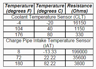
Thanks, kinda saved my ***. Those settings were -7 with a 24900 bias resistor, and 70 with a 249000 bias resistor. Worked well enough to get through the dyno tuning, but it wasn't reading correct. Anyone know the correct bias resistance?
curly is offline  
Old 05-19-2016, 07:43 AM
  #22  
Boost Czar
iTrader: (62)
 
Braineack's Avatar
 
Join Date: May 2005
Location: Chantilly, VA
Posts: 79,507
Total Cats: 4,079
Default

For the MSM:


everything else seem to be okay for you guys?
Attached Thumbnails Help with Braineack built MS3 - fuel pump circuit-80-undefined_0c10a26fffea3c5459ae33247efcaa321785b70e.png   Help with Braineack built MS3 - fuel pump circuit-80-undefined_c71a3d2c6e9fcefe0f243f53f0a651b07ef7bbc4.png  
Braineack is offline  
Old 05-19-2016, 08:52 AM
  #23  
Cpt. Slow
Thread Starter
iTrader: (25)
 
curly's Avatar
 
Join Date: Oct 2005
Location: Oregon City, OR
Posts: 14,224
Total Cats: 1,146
Default

Yes, resistor swap fixed the fuel pump, car dynoed at 247. Much more and he needs injectors/rods.

Alternator sucked, running 11.2-12.7volts the whole time. He said he had some issue with the ecu regulation, on the old ecu, is the MS setup to regulate one? That or he needs a 94-97.
curly is offline  
Old 05-19-2016, 09:03 AM
  #24  
Boost Czar
iTrader: (62)
 
Braineack's Avatar
 
Join Date: May 2005
Location: Chantilly, VA
Posts: 79,507
Total Cats: 4,079
Default

it should be.

double check the voltage at the injectors actually matches what the MS is suggesting. The Alternator settings are on the first tab, and it should be pretty solid at around 14.5v. Those settings are from DIY and are pretty spot on for all other NB installs.
Braineack is offline  
Old 07-21-2016, 11:16 PM
  #25  
Senior Member
iTrader: (8)
 
cyotani's Avatar
 
Join Date: Jan 2012
Location: Azusa, CA
Posts: 1,407
Total Cats: 116
Default

Need help with a fuel pump issue on my MS3X. This is for a 99 using the MSPNP-pro base map.

I'm not able to turn the fuel pump on. Everything else works. When I jump the FP pin on the diagnostics port to force to pump to run and start the car it works just fine. As soon as i disconnect that jumper the FP dies and the car will slowly start to run lean and finally stall when it looses enough pressure.

When I use test mode to trigger the fuel pump I can not hear it running.

I've set it up on the bench in test mode and am reading 0.6V with the output set to off, 4.6V with is set to on, 1.7V when pulsed at 25% DC. So it seems to be functioning. I'm not sure why it's only 4.6 V. Battery in is at 12.4V. The 5V on the proto is 5.08V.

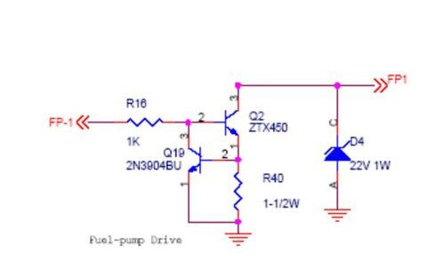
I've attached a picture of the circuit and all diodes look to be the right way. All diodes look to be in the right orientation.

When I swap it back to the stock ECU it primes and starts right away without needing the jumper. I'm stumped

cyotani is offline  
Old 07-21-2016, 11:26 PM
  #26  
Cpt. Slow
Thread Starter
iTrader: (25)
 
curly's Avatar
 
Join Date: Oct 2005
Location: Oregon City, OR
Posts: 14,224
Total Cats: 1,146
Default

It's not providing power to the fuel pump, it's giving the fuel pump relay ground. So you'd wanna check for continuity to ground when switching the fuel pump on/off. But if it has 4.7 volts that's not a good start.
curly is offline  
Old 07-21-2016, 11:36 PM
  #27  
Senior Member
iTrader: (8)
 
cyotani's Avatar
 
Join Date: Jan 2012
Location: Azusa, CA
Posts: 1,407
Total Cats: 116
Default

Originally Posted by curly
It's not providing power to the fuel pump, it's giving the fuel pump relay ground. So you'd wanna check for continuity to ground when switching the fuel pump on/off. But if it has 4.7 volts that's not a good start.
that makes more sense. Well no continuity to ground when I toggle on or off the test mode FP output. Any ideas? It looks like the FP I/O is not user selectable to switch it to a different output.
cyotani is offline  
Old 07-22-2016, 06:47 AM
  #28  
Boost Czar
iTrader: (62)
 
Braineack's Avatar
 
Join Date: May 2005
Location: Chantilly, VA
Posts: 79,507
Total Cats: 4,079
Default

what output do you have the FP on? The MSPNP-PRO map isnt going to match inputs and outputs exactly...
Braineack is offline  
Old 07-22-2016, 10:22 AM
  #29  
Senior Member
iTrader: (8)
 
cyotani's Avatar
 
Join Date: Jan 2012
Location: Azusa, CA
Posts: 1,407
Total Cats: 116
Default

Originally Posted by Braineack
what output do you have the FP on? The MSPNP-PRO map isnt going to match inputs and outputs exactly...
It's maped to the fuel pump pin. the drop down option to re map the output is greyed out and looks like it can not be changed. When I'm in test mode and toggle the fuel pump pin it see a voltage change on the multimeter so the I/O seems to be working from the CPU. I'm guessing I toasted some component when I had my harness miswired earlier.

current plan is to order the components of that circuit and build it on the proto area and bypass the original circuit.
cyotani is offline  
Old 07-22-2016, 10:31 AM
  #30  
Boost Czar
iTrader: (62)
 
Braineack's Avatar
 
Join Date: May 2005
Location: Chantilly, VA
Posts: 79,507
Total Cats: 4,079
Default

well it's completely possible you installed the wrong transistor on Q4
Braineack is offline  
Old 07-22-2016, 10:57 AM
  #31  
Senior Member
iTrader: (8)
 
cyotani's Avatar
 
Join Date: Jan 2012
Location: Azusa, CA
Posts: 1,407
Total Cats: 116
Default

Originally Posted by Braineack
well it's completely possible you installed the wrong transistor on Q4
yup, anything is possible with my noobness on this project.

would it be possible to use i different I/O pin for the fuel pump. It looks like it can not be remaped in the fuel pump setting page. But in the programmable on/off setup one of the inputs is fp_duty. So if I set the fuel pump to open loop pwm then setup a programmable output to trigger on when fp_duty > 0 and wire that to the fuel pump harness pin would that work?

Is there a suitable output on the MSX card to control the FP relay without extra circuitry?
cyotani is offline  
Old 07-22-2016, 11:07 AM
  #32  
SADFab Destructive Testing Engineer
iTrader: (5)
 
aidandj's Avatar
 
Join Date: Apr 2014
Location: Beaverton, USA
Posts: 18,642
Total Cats: 1,866
Default

Why are you using PWM. Do you have a solid state relay?
aidandj is offline  
Old 07-22-2016, 11:21 AM
  #33  
Senior Member
iTrader: (8)
 
cyotani's Avatar
 
Join Date: Jan 2012
Location: Azusa, CA
Posts: 1,407
Total Cats: 116
Default

Originally Posted by aidandj
Why are you using PWM. Do you have a solid state relay?
No, the default FP circuitry is not working. I probably shorted something and damaged a components. I'm trying to figure out a work around. you can not change the maped pin in the Fuel pump set up page. But if I put it to open loop pwm then I should see FP_duty > 0 any time the fuel pump should be running.

Then I can go into the programmable I/O page and setup an output that is triggered to turn on anytime FP_duty is greater than 0. That way it should hopefully match the on/off relay functionality of the FP control as a band aid fix.
cyotani is offline  
Old 07-22-2016, 11:27 AM
  #34  
Boost Czar
iTrader: (62)
 
Braineack's Avatar
 
Join Date: May 2005
Location: Chantilly, VA
Posts: 79,507
Total Cats: 4,079
Default

it won't work as well, since it wont prime with key on and such.


just fix your mistakes!
Braineack is offline  
Old 07-22-2016, 11:34 AM
  #35  
Senior Member
iTrader: (8)
 
cyotani's Avatar
 
Join Date: Jan 2012
Location: Azusa, CA
Posts: 1,407
Total Cats: 116
Default

Originally Posted by Braineack
it won't work as well, since it wont prime with key on and such.


just fix your mistakes!
I agree. The components are on order to rebuild the circuit. I was still curious to try a work around re maping while I wait on those.

Wouldn't a variable speed fuel pump also prime at key on. So wouldn't it have a DC > 0 when it primes and trigger my stock FP relay properly?
cyotani is offline  
Old 07-22-2016, 12:09 PM
  #36  
Boost Czar
iTrader: (62)
 
Braineack's Avatar
 
Join Date: May 2005
Location: Chantilly, VA
Posts: 79,507
Total Cats: 4,079
Default

what'd you need to order? you have a spare component for each thing on that circuit iirc.

look under the board and make sure your soldering to the transistors Q2 and Q19 are good -- no bridged pins.
Braineack is offline  
Old 07-22-2016, 12:18 PM
  #37  
SADFab Destructive Testing Engineer
iTrader: (5)
 
aidandj's Avatar
 
Join Date: Apr 2014
Location: Beaverton, USA
Posts: 18,642
Total Cats: 1,866
Default

Originally Posted by aidandj
For reference here is the fuel pump circuit.


Without r40 the entire circuit is useless.
Probe each point in the circuit.
aidandj is offline  
Old 07-22-2016, 12:21 PM
  #38  
Senior Member
iTrader: (8)
 
cyotani's Avatar
 
Join Date: Jan 2012
Location: Azusa, CA
Posts: 1,407
Total Cats: 116
Default

Originally Posted by Braineack
what'd you need to order? you have a spare component for each thing on that circuit iirc.

look under the board and make sure your soldering to the transistors Q2 and Q19 are good -- no bridged pins.
I should have had a spare of each. But the first time around I built the entire board following the MS3x guide (not frank's writeup). I then troubleshooted a wiring issue since I read the harness pinout wrong. During the troubleshooting I removed every single non needed component from the board so I basically destroyed the spares that I should have had.

Much learning from this project. I'm just glad it's running my engine now except for the FP issue. The end is in sight.

DIY shipped out my order last night so I should be able to rebuild it mid next week.

No solder bridges on the two transistors.
cyotani is offline  
Old 07-22-2016, 08:42 PM
  #39  
Senior Member
iTrader: (8)
 
cyotani's Avatar
 
Join Date: Jan 2012
Location: Azusa, CA
Posts: 1,407
Total Cats: 116
Default

So I gave the re-map "work around" a shot and it worked beautifully. Just in case someone else has a similar problem and stumbles upon this thread and wants to use the temporary band aid solution.

I used the VVT output pin and on the programable I/O page set it to on when FP_duty > 1.

The fuel pump primes on key on like it should and everything works perfectly.
cyotani is offline  
Related Topics
Thread
Thread Starter
Forum
Replies
Last Post
jstck
ECUs and Tuning
25
05-09-2018 03:41 AM
Crarrs
Meet and Greet
11
12-10-2014 09:30 AM
cDc_Geo
Meet and Greet
6
04-01-2012 10:38 AM
Hugh
Miata parts for sale/trade
6
05-10-2011 05:48 PM
jayc72
General Miata Chat
4
01-25-2007 05:39 PM


Quick Reply: Help with Braineack built MS3 - fuel pump circuit


All times are GMT -4. The time now is 08:26 PM.