
Help tracking down MS3 wiring issues/diagram


Thread Starter
Elite Member
Joined: Oct 2013
Posts: 2,764
Total Cats: 951
From: Cedar City, UT
Perfect. Thank you again Zaphod, can't say that enough. If ever in this part of the world feel free to stop by and drive the **** out of my car.
Reply
 0
0

0


once that is done, figuring out what wire goes where will be easily.
I kinda remember making this, where someone was upgrading from a DIYPNP and he wanted me to make his 16pin connector the same.
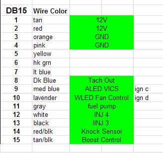
looks like there's at least (2) 12v sources, (2) grounds, Spark C, Spark D, VICS out, WBO2 in, EBC OUT, Knock IN, maybe Tachout is the last, under sure why.
Reply
0
0

Elite Member
Joined: Mar 2006
Posts: 1,574
Total Cats: 106
From: Schwarzenberg, Germany
Hi I think this snipplet gives us the best starting point:
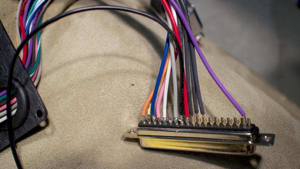
@Jeff - Please post close up pics of that 16pin connector (back) and as Brain said try to see, to which pin on the DB36 connectors the wires are going.
@Brain - I think you missed the two extra injector outputs.
I would be interested to see, how the original owner managed the connection on the two injector connectors (3/4)
Last edited by Zaphod; Jan 30, 2014 at 08:49 AM.
Reply
0
0
Elite Member
Joined: Mar 2006
Posts: 1,574
Total Cats: 106
From: Schwarzenberg, Germany
Yeah, but the car itself was a 93 including the wiring - so there have to be extra wires for the seq. injection - or am I missing something...? And you can see in the DB15 pinout of his DIYPNP that he had 2 extra injection outputs on that DB15...
Reply
0
0
oh maybe not, this is why you gotta trace the harness wires back.
i cant tell if 4Y and 4Z are populated. Doesn't seem to be enough wires on that 16pin to cover it all -- possible it doesn't have any seq. injection outputs populated. dunnoz
i cant tell if 4Y and 4Z are populated. Doesn't seem to be enough wires on that 16pin to cover it all -- possible it doesn't have any seq. injection outputs populated. dunnoz
Reply
1
1
Elite Member
Joined: Mar 2006
Posts: 1,574
Total Cats: 106
From: Schwarzenberg, Germany
O.K. so Jeff the Brain has spoken...- you know what to do - make some good pictures, trace the wires and do a little spreadsheet pin on the extra connector vs. pin on DB36 MS3 or MS3X 
Reply
1
1
Thread Starter
Elite Member
Joined: Oct 2013
Posts: 2,764
Total Cats: 951
From: Cedar City, UT

Reply
0
0
Thread Starter
Elite Member
Joined: Oct 2013
Posts: 2,764
Total Cats: 951
From: Cedar City, UT
Reply
0
0
Thread Starter
Elite Member
Joined: Oct 2013
Posts: 2,764
Total Cats: 951
From: Cedar City, UT
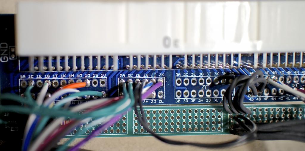
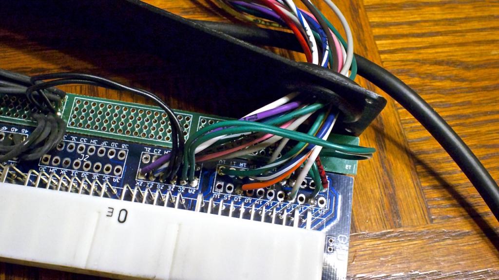
OK Brain, finally got some good pictures of the board for you. I hope this helps.
Pins are labelled as followed
2A 2C 2E 2G 2i 2K
2B 2D 2F 2H 2J 2L
2A 2C 2E 2G 2i 2K
2A-Brown(PIN35)
2C-Red(12VDC)
2E-Orange(IAT)
2G-Pink(02)
2i-Yellow(Coolant)
2K-Green/Yellow(IAC2-A)
2B 2D 2F 2H 2J 2L
2B-Blue(TPS-SIG)
2D-Blue/White(Blank)
2F-White(Blank)
2H-Black(Blank)
2J-Brown(Blank)
2L-No pin in connector
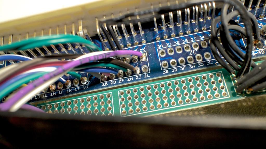
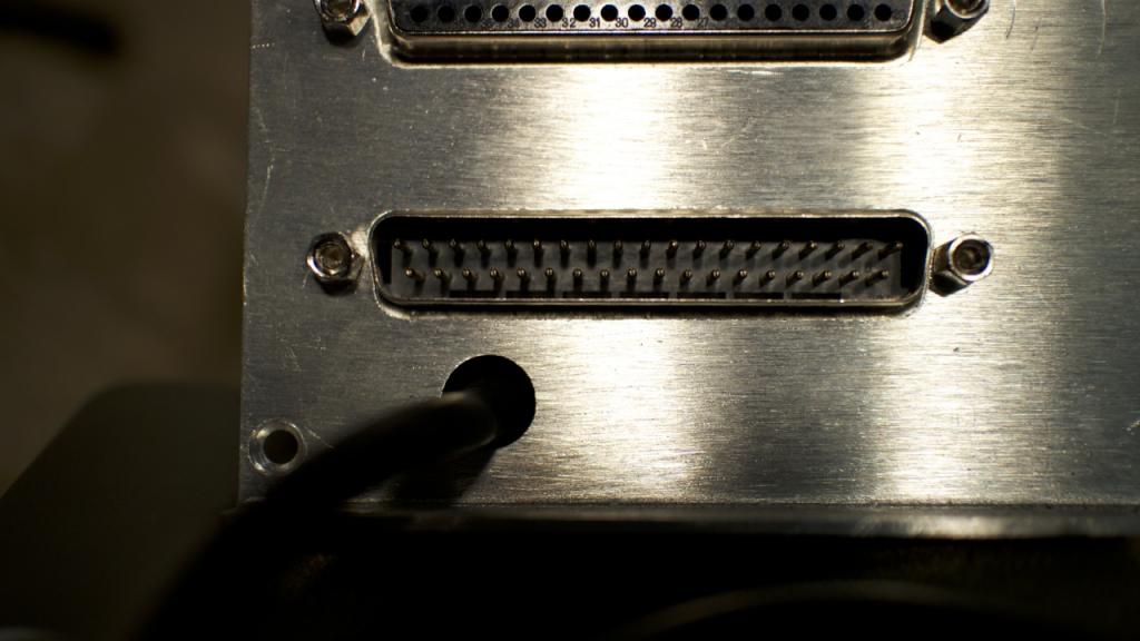
This harness has an odd single pin connector coming off the harness. It is the black wire between red & grey.
The harness goes into this lower port.
Pins are labelled as followed
2A 2C 2E 2G 2i 2K
2B 2D 2F 2H 2J 2L


2A 2C 2E 2G 2i 2K
2A-Brown(PIN35)
2C-Red(12VDC)
2E-Orange(IAT)
2G-Pink(02)
2i-Yellow(Coolant)
2K-Green/Yellow(IAC2-A)
2B 2D 2F 2H 2J 2L
2B-Blue(TPS-SIG)
2D-Blue/White(Blank)
2F-White(Blank)
2H-Black(Blank)
2J-Brown(Blank)
2L-No pin in connector
This harness has an odd single pin connector coming off the harness. It is the black wire between red & grey.

The harness goes into this lower port.

Reply
0
0
I'm still not following where the wires in the first pic end up.
the only thing I can tell from the pics is that
2E and 2G are grounds. That's it. Your pinout listing below the pics doesn't make any sense to me.
you have to trace the wires from 2A-2L all the way back to the harness they are in.
the only thing I can tell from the pics is that
2E and 2G are grounds. That's it. Your pinout listing below the pics doesn't make any sense to me.
you have to trace the wires from 2A-2L all the way back to the harness they are in.
Reply
1
1
Thread Starter
Elite Member
Joined: Oct 2013
Posts: 2,764
Total Cats: 951
From: Cedar City, UT
I'm still not following where the wires in the first pic end up.
the only thing I can tell from the pics is that
2E and 2G are grounds. That's it. Your pinout listing below the pics doesn't make any sense to me.
you have to trace the wires from 2A-2L all the way back to the harness they are in.
the only thing I can tell from the pics is that
2E and 2G are grounds. That's it. Your pinout listing below the pics doesn't make any sense to me.
you have to trace the wires from 2A-2L all the way back to the harness they are in.
The wires on the connector are the ones I paired with the board pinouts.
2A 2C 2E 2G 2i 2K
2A-Brown(PIN35)
2C-Red(12VDC)
2E-Orange(IAT)
2G-Pink(02)
2i-Yellow(Coolant)
2K-Green/Yellow(IAC2-A)
2B 2D 2F 2H 2J 2L
2B-Blue(TPS-SIG)
2D-Blue/White(Blank)
2F-White(Blank)
2H-Black(Blank)
2J-Brown(Blank)
2L-No pin in connector
If you want the actual BOARD wires, I can get that later tonight. Sorry Brain, wasn't sure exactly what you needed.
Reply
0
0
did i not say that like 16 times now?
i need to know where the wires INSIDE the Bob go.
so the green wire on 2A and green wire on 2C and white/blue wire on 2I, etc.
i need to know where the wires INSIDE the Bob go.
so the green wire on 2A and green wire on 2C and white/blue wire on 2I, etc.
Reply
0
0
Thread Starter
Elite Member
Joined: Oct 2013
Posts: 2,764
Total Cats: 951
From: Cedar City, UT
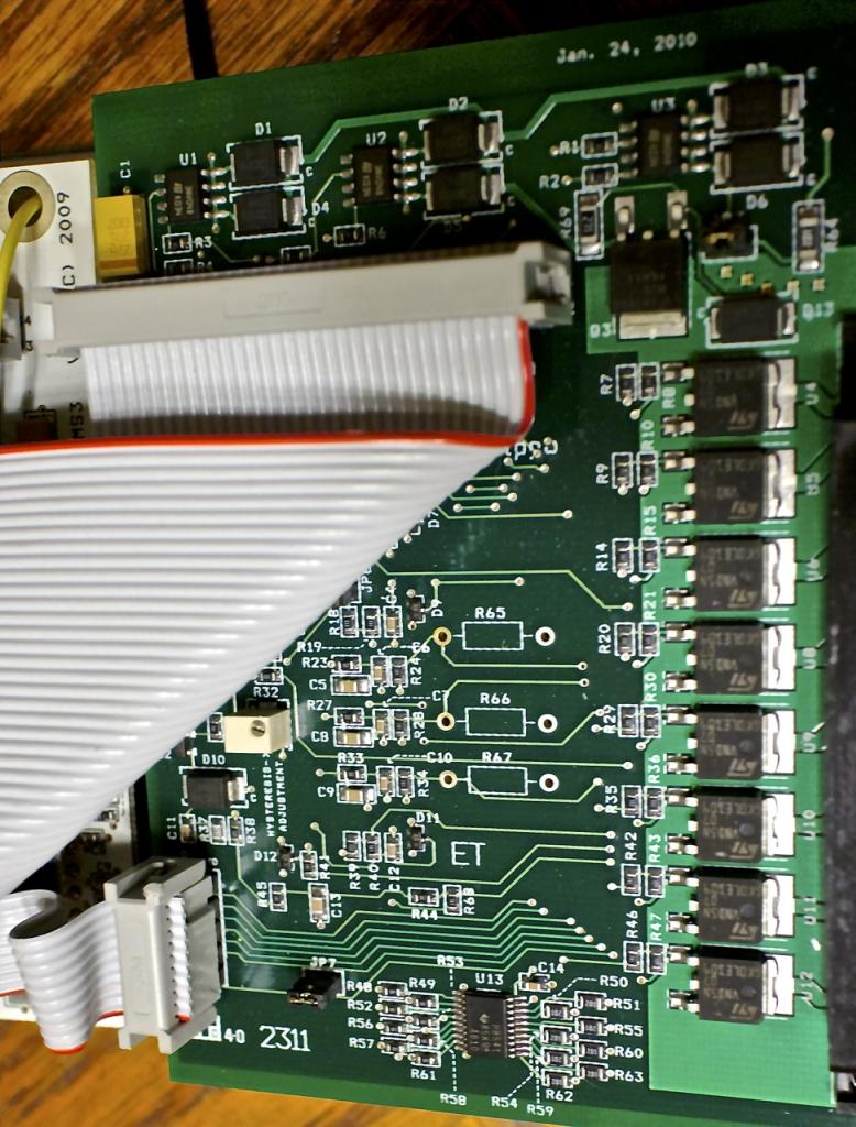
OK Brain here is your info...I hope it helps!
2A 2C 2E 2G 2i 2k
2B 2D 2F 2H 2J 2L
Harness wiring
2 Green Wires———— 2A/2C
2 Black Grounds——————2E/2G
White/blue=IAC1-B—-2I
Purple=Fuel Pump—--2K
Grey=TPS-VREF——2B
Pink=02——————-2D
Blue/white=IAC1-A—--2F
Green/white=IAC2-B—--2H
Brown=PIN36—---------2J
no wire present———2L
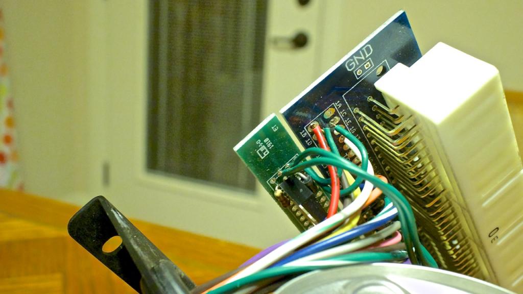
I was trying to find IAC2-A and found it on 1G
The 2 greens on 2A 2C terminate on the end of the board but there are no markings on the wires/board to indicate why.

2A 2C 2E 2G 2i 2k
2B 2D 2F 2H 2J 2L
Harness wiring
2 Green Wires———— 2A/2C
2 Black Grounds——————2E/2G
White/blue=IAC1-B—-2I
Purple=Fuel Pump—--2K
Grey=TPS-VREF——2B
Pink=02——————-2D
Blue/white=IAC1-A—--2F
Green/white=IAC2-B—--2H
Brown=PIN36—---------2J
no wire present———2L
I was trying to find IAC2-A and found it on 1G
The 2 greens on 2A 2C terminate on the end of the board but there are no markings on the wires/board to indicate why.


Last edited by Jeffbucc; Mar 15, 2014 at 12:37 AM.
Reply
0
0


