
idel is ruogh, plugs are black


if the triggers were switched it wouldnt run.
are you sure you cut your injector leads into the stock ecu, you dont have control over the fuel for some reason. it may be the PWM circuit, where you jumped the resistors on the heatsink. I'll reread the megamanual about that when i get home....or you can
are you sure you cut your injector leads into the stock ecu, you dont have control over the fuel for some reason. it may be the PWM circuit, where you jumped the resistors on the heatsink. I'll reread the megamanual about that when i get home....or you can
Reply
 0
0

0

Thread Starter
Elite Member
iTrader: (12)
Joined: Jan 2007
Posts: 2,573
Total Cats: 12
From: Hermosa Beach, CA
Even if the stock ecu was connected to the injectors (which it isent) it would still run, I currently have the car on the stock ecu right now so I can drive the car.
Ill see if I can find anything in the megamanual.. thanks.
Ill see if I can find anything in the megamanual.. thanks.
Reply
0
0
Thread Starter
Elite Member
iTrader: (12)
Joined: Jan 2007
Posts: 2,573
Total Cats: 12
From: Hermosa Beach, CA
71. It is choice time yet again. You have to decide whether to install the current limit circuit for driver FET protection. This clamps the current to ~14 Amps, and it is recommended that most people install this. To install the current limit protect circuit:
Install R37 {TAH20PR050JE-ND}. It goes on the heat sink, however it does not have a mounting hole. You can use double sided thermal transfer tape {BER158-ND} to fasten it to the heat sink, however this is quite expensive if you are just doing two resistors.
Install R38 {TAH20PR050JE-ND}. It goes on the heat sink as well, however it does not have a mounting hole. You can use double sided thermal transfer tape {BER158-ND} to fasten it to the heat sink, however this is quite expensive if you are just doing two resistors.
There are no jumpers to install.
However, the circuit can be omitted if protection is not required or desired - in this case install jumpers in place of R37 and R38.
72. IF you installed R37 and R38 in the previous step, install Q14 and Q15 {2N3904FS-ND} - otherwise you can leave then out. It does no harm to install them in every case, however. Use a clean tip, and be careful not to bridge the closely spaced pins.
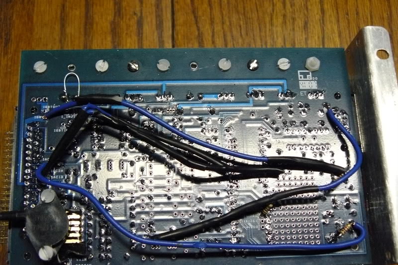
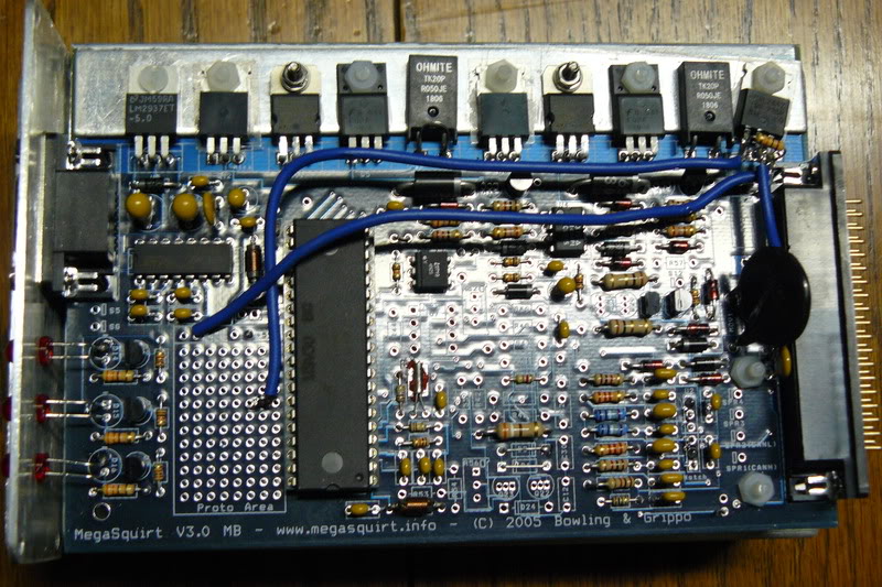
According to that, I should be fine. I have Q14 and Q15 out, and R37 and R38 are jumped. Of course I jumped r37 and r38 while they are still on he bord (showen in the picture). That shouldent effect anything correct?
Install R37 {TAH20PR050JE-ND}. It goes on the heat sink, however it does not have a mounting hole. You can use double sided thermal transfer tape {BER158-ND} to fasten it to the heat sink, however this is quite expensive if you are just doing two resistors.
Install R38 {TAH20PR050JE-ND}. It goes on the heat sink as well, however it does not have a mounting hole. You can use double sided thermal transfer tape {BER158-ND} to fasten it to the heat sink, however this is quite expensive if you are just doing two resistors.
There are no jumpers to install.
However, the circuit can be omitted if protection is not required or desired - in this case install jumpers in place of R37 and R38.
72. IF you installed R37 and R38 in the previous step, install Q14 and Q15 {2N3904FS-ND} - otherwise you can leave then out. It does no harm to install them in every case, however. Use a clean tip, and be careful not to bridge the closely spaced pins.
According to that, I should be fine. I have Q14 and Q15 out, and R37 and R38 are jumped. Of course I jumped r37 and r38 while they are still on he bord (showen in the picture). That shouldent effect anything correct?
Reply
0
0
Um, if the car tells the injector to open for 3ms, then the MS tells it to open for 2.5ms a little bit later, it'll get twice the fuel it wants.
Reply
0
0
71. It is choice time yet again. You have to decide whether to install the current limit circuit for driver FET protection. This clamps the current to ~14 Amps, and it is recommended that most people install this. To install the current limit protect circuit:
According to that, I should be fine. I have Q14 and Q15 out, and R37 and R38 are jumped. Of course I jumped r37 and r38 while they are still on he bord (showen in the picture). That shouldent effect anything correct?
According to that, I should be fine. I have Q14 and Q15 out, and R37 and R38 are jumped. Of course I jumped r37 and r38 while they are still on he bord (showen in the picture). That shouldent effect anything correct?
Reply
0
0
Maybe he should just complete the board and then he wouldn't have to worry about it 
I'm a big fan of doing more than you need to JIC so you don't have to worry about that being the problem.
I'm a big fan of doing more than you need to JIC so you don't have to worry about that being the problem.
Reply
0
0
Thread Starter
Elite Member
iTrader: (12)
Joined: Jan 2007
Posts: 2,573
Total Cats: 12
From: Hermosa Beach, CA
PICS ARE HERE
http://i53.photobucket.com/albums/g4.../MS/ms3002.jpg
http://i53.photobucket.com/albums/g4.../MS/ms3001.jpg
I cant really put Q14 and Q15 back on, I think I messed them up takeing them out when I bidged the solders.
http://i53.photobucket.com/albums/g4.../MS/ms3002.jpg
http://i53.photobucket.com/albums/g4.../MS/ms3001.jpg
I cant really put Q14 and Q15 back on, I think I messed them up takeing them out when I bidged the solders.
Reply
0
0

Newb
Joined: Jul 2007
Posts: 18
Total Cats: 0
From: Stockholm Sweden
Reply
0
0
PICS ARE HERE
http://i53.photobucket.com/albums/g4.../MS/ms3002.jpg
http://i53.photobucket.com/albums/g4.../MS/ms3001.jpg
I cant really put Q14 and Q15 back on, I think I messed them up takeing them out when I bidged the solders.
http://i53.photobucket.com/albums/g4.../MS/ms3002.jpg
http://i53.photobucket.com/albums/g4.../MS/ms3001.jpg
I cant really put Q14 and Q15 back on, I think I messed them up takeing them out when I bidged the solders.
Reply
0
0
www.tinyurl.com
But, more to the point, when you insert it as a pic it works... Or,I guess you could make it a LINK instead of just writing it in
Example:
http://tinyurl.com/324tpk
Single click on a button on my toolbar.
But, more to the point, when you insert it as a pic it works... Or,I guess you could make it a LINK instead of just writing it in
Example:
http://tinyurl.com/324tpk
Single click on a button on my toolbar.
Reply
0
0
I'd say adjust req fuel lower to lean it out till it runs right. Easy and might do it. Try 10, 8,6, etc. Couldn't hurt. Also pull up a pulse width guage in MegaTune and see what it's doing while it's running. Try doing a datalog while it's running shitty and show us your datalog.
Reply
0
0
I'd say adjust req fuel lower to lean it out till it runs right. Easy and might do it. Try 10, 8,6, etc. Couldn't hurt. Also pull up a pulse width guage in MegaTune and see what it's doing while it's running. Try doing a datalog while it's running shitty and show us your datalog.
Reply
0
0


