
MSIII v3.57 No CAS or CAM


Because race car.
You really can't test the sensors' output with a standard multimeter while cranking. You need a scope for that, and you can monitor conditioner input and conditioner output to make sure your VR pots are in the right ball park.
There is really only one useful test you can do with the multimeter to test for sensor functionality. Pull plugs, spin motor by hand. Probe the sensor output. You should see CKP switch between 0V and (appx) 5V 4 times per revolution. You should see CMP switch between 0V and (appx) 5V three times per every two revolutions.
To check soundness of your wiring, you can continuity check from CKP output pin to pin 24 on the MS main board. You can do the same check from CMP output to the pin you are using for cam input, JS10 or Expander 32 depending on how you did it.
Also since you were playing with trigger wheels, double check that you did not install the wheel backwards.

Swapped them back to 12v
Since we have a running NB car waiting to be transformed, I pulled the sensor set out of it and installed it. Still no signals showing up in the composite logger.
We have a new MSIII coming tomorrow. Possibly an oscilloscope, too. Unless there is a problem in our tune settings, I am at a loss for what else to try.
There is really only one useful test you can do with the multimeter to test for sensor functionality. Pull plugs, spin motor by hand. Probe the sensor output. You should see CKP switch between 0V and (appx) 5V 4 times per revolution. You should see CMP switch between 0V and (appx) 5V three times per every two revolutions.
To check soundness of your wiring, you can continuity check from CKP output pin to pin 24 on the MS main board. You can do the same check from CMP output to the pin you are using for cam input, JS10 or Expander 32 depending on how you did it.
Also since you were playing with trigger wheels, double check that you did not install the wheel backwards.

Reply
 0
0

0

Thread Starter
Junior Member
Joined: Apr 2010
Posts: 250
Total Cats: 125
From: Laguna Niguel
We are still not running, with no change from yesterday.
We have been testing sensors, comparing between a running 99 with a DIYPNP and the MSIII 2001+
With the computers plugged in, probing the crank sensor wires with a multimeter, we see ~1.66 v at rest and ~1.77 v during cranking. This is consistent between the two cars. With the computers disconnected, I see .01 v static with ~.8v as the tooth passes the sensor. This is the same between the two cars. I then tested between pins 8 and 24 on the MSIII main harness, with the same results (.01 to .8v).
Anyone have any ideas about settings that I have not set right? Possibly a base map?
Reply
0
0
Please read post #21 and do the tests I describe. Testing with a multimeter while cranking is pretty much worthless. Testing with the ECU unplugged is pretty much worthless.
What are you doing with pin 8?
What are you doing with pin 8?
Reply
0
0

Newb
Joined: Oct 2010
Posts: 10
Total Cats: 0
That exactly happens to me although is not the same car that I got. I resolve that working the r52 and r56 pots. Set both pots to zero and work with the r56 one turn clockwise at a time and check until you got a crank signal.
Your cam signal seems to look good.
Your cam signal seems to look good.
Reply
0
0

Joined: Sep 2005
Posts: 34,434
Total Cats: 7,549
From: Chicago. (The less-murder part.)
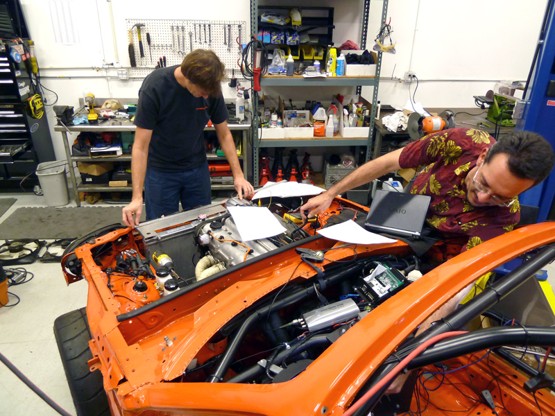
After a call from Emilio (I didn't realize when I first saw this thread that it was his car) I drove up to 949's shop this evening, and after a long night (thanks for the beer and the burritos, by the way) it's all fixed and the engine is running.
The problem was that R56 on the main board and R11 on the MS3X board were set near the bottom of their range. These pots create the reference voltage which the op-amps compare the incoming signal to. With an open-collector sensor, the output voltage never quite drops all the way to zero, and the reference voltage was set just slightly below the "low" voltage from the sensors.
Apparently the documentation doesn't really talk about this, but it's fairly easy to adjust on the bench with nothing more than a voltmeter- no need for guesswork and blindly turning pots. For the main board, measure the voltage between R54 and pin 3 of U7 while turning R56. On the X board, measure between R17 and pin 3 of U7 while turning R11. In both cases, you want to see about 2.5 to 3 volts at that point, which puts you right in the middle of the actual output range of the sensors.
Incidentally, John, I was impressed by the job you did on the wiring. It all came out rather nicely.
One thing- where the wires (and the MAP sensor hose) penetrate the firewall, you really need to stick a grommet and/or some putty around there- those lines are all going to be cut to shreds on the track.
Reply
0
0
After a call from Emilio (I didn't realize when I first saw this thread that it was his car) I drove up to 949's shop this evening, and after a long night (thanks for the beer and the burritos, by the way) it's all fixed and the engine is running.
The problem was that R56 on the main board and R11 on the MS3X board were set near the bottom of their range. These pots create the reference voltage which the op-amps compare the incoming signal to. With an open-collector sensor, the output voltage never quite drops all the way to zero, and the reference voltage was set just slightly below the "low" voltage from the sensors.
Apparently the documentation doesn't really talk about this, but it's fairly easy to adjust on the bench with nothing more than a voltmeter- no need for guesswork and blindly turning pots. For the main board, measure the voltage between R54 and pin 3 of U7 while turning R56. On the X board, measure between R17 and pin 3 of U7 while turning R11. In both cases, you want to see about 2.5 to 3 volts at that point, which puts you right in the middle of the actual output range of the sensors.
Incidentally, John, I was impressed by the job you did on the wiring. It all came out rather nicely.
One thing- where the wires (and the MAP sensor hose) penetrate the firewall, you really need to stick a grommet and/or some putty around there- those lines are all going to be cut to shreds on the track.
The problem was that R56 on the main board and R11 on the MS3X board were set near the bottom of their range. These pots create the reference voltage which the op-amps compare the incoming signal to. With an open-collector sensor, the output voltage never quite drops all the way to zero, and the reference voltage was set just slightly below the "low" voltage from the sensors.
Apparently the documentation doesn't really talk about this, but it's fairly easy to adjust on the bench with nothing more than a voltmeter- no need for guesswork and blindly turning pots. For the main board, measure the voltage between R54 and pin 3 of U7 while turning R56. On the X board, measure between R17 and pin 3 of U7 while turning R11. In both cases, you want to see about 2.5 to 3 volts at that point, which puts you right in the middle of the actual output range of the sensors.
Incidentally, John, I was impressed by the job you did on the wiring. It all came out rather nicely.
One thing- where the wires (and the MAP sensor hose) penetrate the firewall, you really need to stick a grommet and/or some putty around there- those lines are all going to be cut to shreds on the track.
Grommet for that umbilical is on the list. All holes in the firewall need to be positively plugged to pass tech so it would need to be done anyway.
Yeah, John builds a damn nice car.

__________________


Reply
0
0

The problem was that R56 on the main board and R11 on the MS3X board were set near the bottom of their range....
Apparently the documentation doesn't really talk about this, but it's fairly easy to adjust on the bench with nothing more than a voltmeter- no need for guesswork and blindly turning pots.
Apparently the documentation doesn't really talk about this, but it's fairly easy to adjust on the bench with nothing more than a voltmeter- no need for guesswork and blindly turning pots.
from msextra docs:
d) With a small screwdriver, turn the pots, R52 and R56, about 12 turns to the fully anticlockwise position (you may feel a "click") and then turn R56 back about 6 turns clockwise.
JP7 is a jumper for a pullup on the "Cam" input. This is typically required with hall or optical sensor inputs. It should not be used with VR sensor inputs.
When using hall or optical sensors inputs, the cam input adjustment potentiometers should be set as follows. Turn both pots (R11 and R32) full anti-clockwise - approx five turns. Then turn the top one (R11) two turns clockwise.
When using a VR (magnetic) sensor input, the cam input adjustment potentiometers should be set as follows. Turn both pots (R11 and R32) full anti-clockwise - approx five turns. This is usually the right setting.
Reply
0
0
Joined: Sep 2005
Posts: 34,434
Total Cats: 7,549
From: Chicago. (The less-murder part.)
Hmm. Didn't see that when I searched.
Six turns on R56 might be about right, but two turns on R11 would be cutting it really close. I seem to recall having to crank that one quite a lot to get the reference into the 3 volt range. I'm sure it would run at a lower reference voltage, but why not set it optimally to give you the most safety margin?
Six turns on R56 might be about right, but two turns on R11 would be cutting it really close. I seem to recall having to crank that one quite a lot to get the reference into the 3 volt range. I'm sure it would run at a lower reference voltage, but why not set it optimally to give you the most safety margin?
Reply
0
0
Thread Starter
Junior Member
Joined: Apr 2010
Posts: 250
Total Cats: 125
From: Laguna Niguel
I finally have had enough time off to come back and say thanks to Joe for coming down and bailing us out.
Had to do a few 20 hour days to get the car ready for a race last weekend, which really kept me offline for a while. Other than a few minor issues, the car ran well enough to complete about 6 hours worth of hard track time. We were pretty happy considering that it had absolutely no shakedown time before the races.
Thanks to everyone here who takes the time to help us "electronics challenged" folks out.
John
Reply
0
0
Joined: Sep 2005
Posts: 34,434
Total Cats: 7,549
From: Chicago. (The less-murder part.)
Glad to hear it- that was a pretty monumental task you guys accomplished. One of these days I want to see the car all buttoned up and rolling!
Reply
0
0
The cool thing about lofty goals is that sometimes you reach them.
__________________
Reply
0
0

Reply
0
0
Joined: Sep 2005
Posts: 34,434
Total Cats: 7,549
From: Chicago. (The less-murder part.)
Beautiful!
I was really impressed by those LED lights in the shop- a lot brighter than I'd have expected. How's the actual pattern work out in the real world?
I was really impressed by those LED lights in the shop- a lot brighter than I'd have expected. How's the actual pattern work out in the real world?
Reply
0
0
We had a working config a few races ago but decided to experiment with the low mount. Too low and aimed wrong for last weekends race. Have to mount the spot beams higher up and re-aim like we had them before.
__________________
Reply
0
0

Thread
Thread Starter
Forum
Replies
Last Post
AlwaysBroken
Engine Performance
4
Sep 4, 2015 01:35 PM


