Take a look at my board. Help me sort and prep my MS.
 08-11-2008, 02:56 PM
#1
Senior Member
Thread Starter
iTrader: (10)

Join Date: Apr 2007
Location: Ohio
Posts: 782
Total Cats: 4
Just wanting the gurus and others more experienced than I to look at my board and advise on a couple of issues.
This is a Braineak build but I believe this was an early one. It was also built for a 1.6 and I’m using it on a 1.8. We’ve discussed it but not in detail and I feel like I’m being a pest so I’m putting it out here for help.
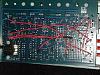
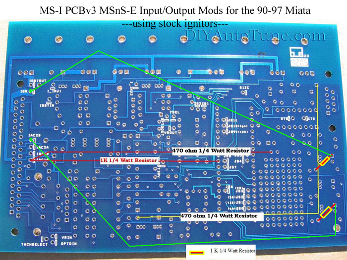
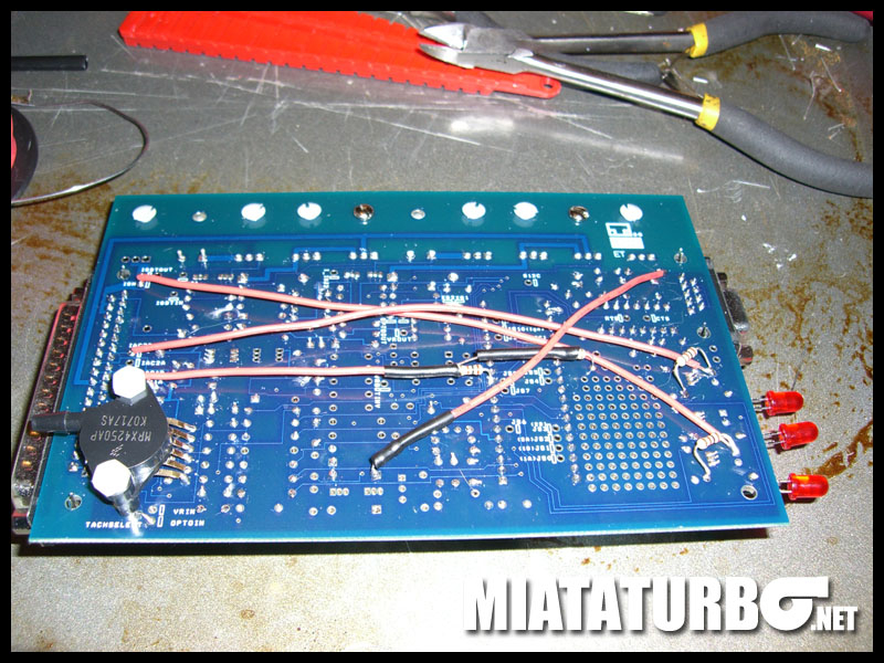
First – Going through Brain’s “how to”, there’s a pic that shows the spark outputs reversed from the graphic. He noted not to duplicate his but my board matches his photo, not the graphic. So I’m wondering if I should leave mine as is or reverse it.
Graphic:
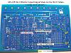
Scott’s pic:
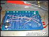
My board:
Second – My board does not have the .1µF capacitor on the tach input circuit from JS8 to ground. Should I add this? If so, can I use the same ground pin as the EBC MOSFET?
Third – I’m pretty certain the LEDs are backwards, no?
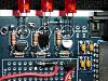
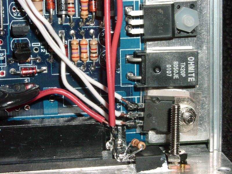
I also have a 100k resistor on the EBC (@ JS2), so I need to change this to a 100 ohm and add a mica insulator on the IRLZ44. Right? Do I need to re-attach the MOSFET with a nylon screw or will the metal one still be OK? It's mounted to the front of the case.
Lastly – I believe I need to add a diode for the idle mod. What diode do I use? I’m planning a parallel install for now so I suppose it doesn’t matter, but I’d just as soon do it now while I’m monkeying about with it.

Whew! Thanks for takin’ a look. Once this is sorted I guess it’s on to the parallel harness changes. THAT should be interesting……
This is a Braineak build but I believe this was an early one. It was also built for a 1.6 and I’m using it on a 1.8. We’ve discussed it but not in detail and I feel like I’m being a pest so I’m putting it out here for help.
First – Going through Brain’s “how to”, there’s a pic that shows the spark outputs reversed from the graphic. He noted not to duplicate his but my board matches his photo, not the graphic. So I’m wondering if I should leave mine as is or reverse it.
Graphic:
Scott’s pic:
My board:

Second – My board does not have the .1µF capacitor on the tach input circuit from JS8 to ground. Should I add this? If so, can I use the same ground pin as the EBC MOSFET?
Third – I’m pretty certain the LEDs are backwards, no?

I also have a 100k resistor on the EBC (@ JS2), so I need to change this to a 100 ohm and add a mica insulator on the IRLZ44. Right? Do I need to re-attach the MOSFET with a nylon screw or will the metal one still be OK? It's mounted to the front of the case.
Lastly – I believe I need to add a diode for the idle mod. What diode do I use? I’m planning a parallel install for now so I suppose it doesn’t matter, but I’d just as soon do it now while I’m monkeying about with it.
Whew! Thanks for takin’ a look. Once this is sorted I guess it’s on to the parallel harness changes. THAT should be interesting……
Last edited by soloracer; 08-11-2008 at 04:45 PM. Reason: Giant pics

Reply
 0
0

0
08-11-2008, 03:07 PM
#2
Boost Czar


iTrader: (62)
Join Date: May 2005
Location: Chantilly, VA
Posts: 79,494
Total Cats: 4,080
First – Going through Brain’s “how to”, there’s a pic that shows the spark outputs reversed from the graphic. He noted not to duplicate his but my board matches his photo, not the graphic. So I’m wondering if I should leave mine as is or reverse it.
Second – My board does not have the .1µF capacitor on the tach input circuit from JS8 to ground. Should I add this? If so, can I use the same ground pin as the EBC MOSFET?
Third – I’m pretty certain the LEDs are backwards, no?
I also have a 100k resistor on the EBC (@ JS2), so I need to change this to a 100 ohm and add a mica insulator on the IRLZ44.
Right? Do I need to re-attach the MOSFET with a nylon screw or will the metal one still be OK? It's mounted to the front of the case.
Lastly – I believe I need to add a diode for the idle mod. What diode do I use? I’m planning a parallel install for now so I suppose it doesn’t matter, but I’d just as soon do it now while I’m monkeying about with it.
like this:

any 1A diode should work
http://www.radioshack.com/product/in...Id=2062589&cp=
Reply
0
0
08-11-2008, 03:11 PM
#3
Junior Member

Join Date: Aug 2007
Posts: 115
Total Cats: 0
Follow the DIY guide as far as spark goes.
You need the capacitor on the tach signal if you want to run the Hi-res code.
Not so sure on teh EBC stuff, but if you are insulating it with mica for the love of god don't un-insulate it with a metal screw.
For the idle stuff, you can probably get away with just about any power diode (think 1n4001, 1n4004, 1n5404, etc.).
or
word on what Braineak said
Reply
0
0
08-11-2008, 03:20 PM
#4
Senior Member
Thread Starter
iTrader: (10)
Join Date: Apr 2007
Location: Ohio
Posts: 782
Total Cats: 4
...you actually can put a diode on both those the Idle and EBC FETs right there on the board. stripe side to s12, then on to each of the middle legs of the FETs."
Thanks Brain!
For the idle stuff, you can probably get away with just about any power diode (think 1n4001, 1n4004, 1n5404, etc.).
Last edited by soloracer; 08-11-2008 at 03:22 PM. Reason: stupid me left out quote tag!
Reply
0
0
08-11-2008, 03:26 PM
#5
Boost Czar
iTrader: (62)
Join Date: May 2005
Location: Chantilly, VA
Posts: 79,494
Total Cats: 4,080
1 for each.
regarding the EBC. when I first started doing them, DIY didn't send them with any insulators and I had no clue they needed them. The resistor was their mistake as well as the package was actually labeled 100ohms but had 100k ohm resistors instead.
regarding the EBC. when I first started doing them, DIY didn't send them with any insulators and I had no clue they needed them. The resistor was their mistake as well as the package was actually labeled 100ohms but had 100k ohm resistors instead.
Reply
0
0
08-11-2008, 03:42 PM
#7
Senior Member
Thread Starter
iTrader: (10)
Join Date: Apr 2007
Location: Ohio
Posts: 782
Total Cats: 4

Any thoughts on what I need to do with that harness?
Also, what's the diode on the EBC for?
Reply
0
0
08-11-2008, 03:47 PM
#8
Boost Czar
iTrader: (62)
Join Date: May 2005
Location: Chantilly, VA
Posts: 79,494
Total Cats: 4,080
same reason it's on the idle valve...the prevent voltage spikes and whatnot.
for the harness...you can compare the two diagrams and see where you need to move wires...it's not many..
injector wires need to be split to 2Y and 2Z
TPS input should be added
Probably want to connect all four ground spots (2A, 2B, 2C, 2D)
fuel pump ground to 2T
that should be it, not much is different.
Reply
0
0
08-12-2008, 10:25 AM
#10
Supporting Vendor

Join Date: Sep 2006
Posts: 2,332
Total Cats: 67
For the record, all firmware versions can benefit from the cap mod. We discovered the benefits from the cap mod while hunting down a misfire issue with regular MS1/Extra, and it's been standard on the MSPNP ever since.
Reply
0
0
08-14-2008, 11:25 PM
#11
Senior Member
Thread Starter
iTrader: (10)
Join Date: Apr 2007
Location: Ohio
Posts: 782
Total Cats: 4
OK. All updates, revisions, corrections, complete on the board. The harness awaits...
I have one question about the diodes for idle and EBC. I tied the banded ends together and soldered to the board (ran the other side to the center legs of the FETs). I assume this is ok?
I have one question about the diodes for idle and EBC. I tied the banded ends together and soldered to the board (ran the other side to the center legs of the FETs). I assume this is ok?
Reply
0
0

Thread
Thread Starter
Forum
Replies
Last Post
Zaphod
MEGAsquirt
47
10-26-2018 11:00 PM
Mikel
MEGAsquirt
4
09-28-2015 04:46 PM


