
vvt tuner wiring help!


its just how i drew it. based on this:
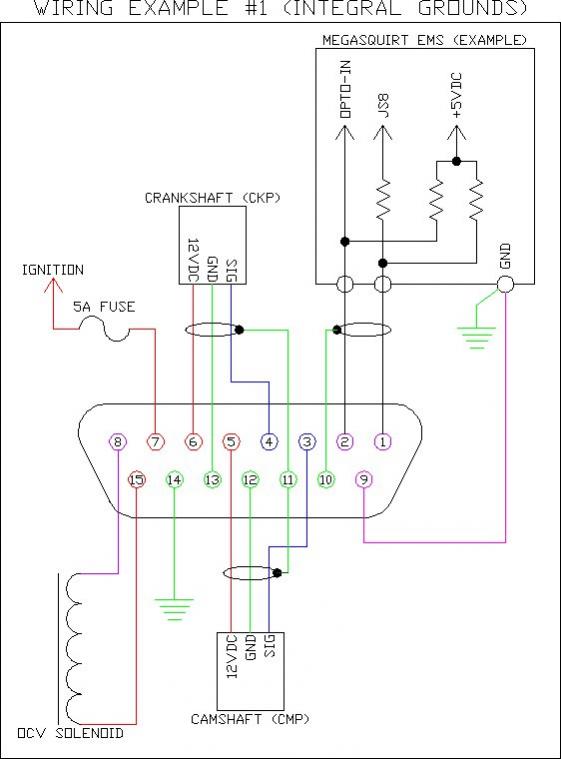
you should be able simply splice/tap into all the wires but the ones going to pin 1-2-3-4; those wires need to be cut, feed into the vvtuner, then back out to the ecu plug via pins 1 and 2. Basically you're sending the cmp/ckp signals into the VVTuner first, then out to the MS.
I kinda drew it wrong as I was thinking 1 and 2 are the inputs, not the outputs.
omfg, and I also forgot pin 7 to W/R 4AF. I suck.
try this:
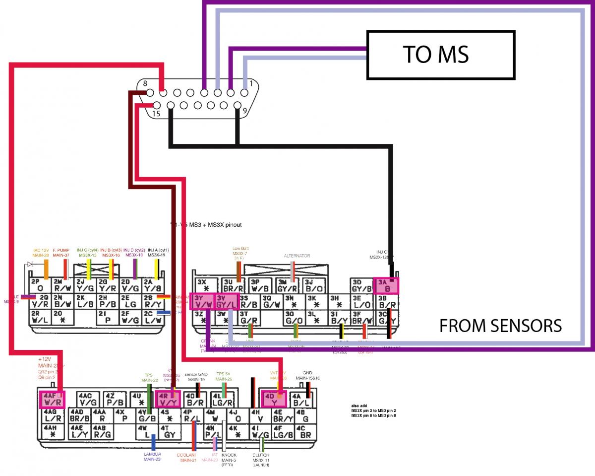
Reply
 0
0

0
Thread Starter
Senior Member
iTrader: (1)
Joined: May 2010
Posts: 581
Total Cats: 8
From: Harrisburg, Pa
I will try that. I'm just confused as I'm pretty sure I already have it connected like that. which is what's making me crazy and why I think I must have damaged the unit.
I know all of the sensors are still good because I switch everything back and can drive the car just fine.
I measured voltages and stuff last night and everything seemed ok? I'm not entirely sure because I'm not entirely sure what everything should be getting.
I know all of the sensors are still good because I switch everything back and can drive the car just fine.
I measured voltages and stuff last night and everything seemed ok? I'm not entirely sure because I'm not entirely sure what everything should be getting.
Reply
0
0
Thread Starter
Senior Member
iTrader: (1)
Joined: May 2010
Posts: 581
Total Cats: 8
From: Harrisburg, Pa
So finally they told me to pull R2 and R3 and just run it parallel. It starts but won't run for more then a few seconds and like ****. I will start tuning and see what comes of it.
Edit: But first does this look normal?
Edit: But first does this look normal?
Reply
0
0
Thread Starter
Senior Member
iTrader: (1)
Joined: May 2010
Posts: 581
Total Cats: 8
From: Harrisburg, Pa
Thought I'd share with everyone that I was able to get it working. I re-instated the resistors DIY told me to remove and moved the OPTO from the 12v to 5v. Fired right up and idled just like normal. I'll upload a video later but yeah I guess that's a major issue if you're sharing sensors you have to change the opto from 12v to 5v
Reply
0
0
this is why i wanted that composite log we would have been able to see that the sensor was dropping out. and then i would have remembered this same fix from someone else over on m.net.
Reply
0
0

Thought I'd share with everyone that I was able to get it working. I re-instated the resistors DIY told me to remove and moved the OPTO from the 12v to 5v. Fired right up and idled just like normal. I'll upload a video later but yeah I guess that's a major issue if you're sharing sensors you have to change the opto from 12v to 5v
i'm in just about exactly the same situation as you except i didn't go to wiring the vvt box for power outside of megasquirt - my vvt box has been getting power and comm all along thru ms, just not running ocv like it's supposed to
anyhow
i'm about to try changing opt 0 from 12v to 5v
just one quick question if you're still out there
when it finally started up were you on the totally normal base map?
i mean the pid settings it starts with? and how about the output trigger type? inverted for nb or passthru for nb?
thanks
chris
Reply
0
0
Thread Starter
Senior Member
iTrader: (1)
Joined: May 2010
Posts: 581
Total Cats: 8
From: Harrisburg, Pa
It idled totally normal. I drove around with autotune on for awhile to let the rest of the tune get adjusted.
Also its not opt 0 its literally opto, that's how I read it printed on the board anyway.
Its a fairly straight forward fix though, should be a column of resistors and (in my case anyway) opto was the only one with an end in the 12v column
Also its not opt 0 its literally opto, that's how I read it printed on the board anyway.
Its a fairly straight forward fix though, should be a column of resistors and (in my case anyway) opto was the only one with an end in the 12v column
Reply
1
1
It idled totally normal. I drove around with autotune on for awhile to let the rest of the tune get adjusted.
Also its not opt 0 its literally opto, that's how I read it printed on the board anyway.
Its a fairly straight forward fix though, should be a column of resistors and (in my case anyway) opto was the only one with an end in the 12v column
Also its not opt 0 its literally opto, that's how I read it printed on the board anyway.
Its a fairly straight forward fix though, should be a column of resistors and (in my case anyway) opto was the only one with an end in the 12v column
i''ve got the board out now and i'm looking right at the resistor
i'm still curious about those settings for your pid and output trigger type?
i'm most interested in the output trigger type
did you use passthru or inverted for nb?
Reply
0
0


