When you click on links to various merchants on this site and make a purchase, this can result in this site earning a commission. Affiliate programs and affiliations include, but are not limited to, the eBay Partner Network.
Yeah Mobius, they're 1st gen though, and I don't know if the valving has been tweaked 'because racecar'. One way to find out though ... the worst that can happen is that they come off again, in which case I might be talking to you about those springs Lachy.
Thanks for that link Lachy, I just can't get over the price differences for a pressure sensor compared to a temperature one but I just have to bite the bullet.
I HAVE a hoist. It's a lazy bastard though, just lays there on it's side ... Currently doing a bit of housekeeping there to tidy the floor in prep for getting it up, finally found the instructions which set out the measurements for bolting down the base so I am pretty much good to go. The hoist is a two post I got for a good price from a deceased estate and it will make a big difference, what with decent lighting now, a gas space heater and the walls and roof fully lined with R2 insulation. When I have it operational I might put a post in the sheds thread, but they are palaces there ...
I am going to have to watch myself driving this thing. I have a 'favourite' roundabout, and I went through it so fast today that I passed a string of traffic in the left lane on the exit, I must have been a blur to them. Almost legal, but the speed differential made it seem like they were stopped, and if Plod had been watching ... it could have been a bad day. I need to get back on the track real bad. Or maybe just drive the Falcon wagon more.
There has been a bit happening lately, had first track day and got into low/mid 11s at Wakefield (~2sec off the racecar's best), it is certainly a very different beast to the racecar! Brakes didn't seem to be confidence-inspiring, but at least I got some seat time.
Also, very pleased that it sailed through rego inspection with the 3in DP-to-tip exhaust, I was expecting to have to change it but though I would roll the dice, so that was a pleasant surprise.
Second track day! Down to 1:10.0, a few tenths off the racecar time. I might have got there but the piping to the air filter was pulling off the filter neck, probably due to a failed LH engine mount. Rather than risk things further, I called it quits.
Flat through the kink, ~170kmh, ...
... then hard braking for T2.
This time the car was much more planted, the brakes seemed much better, and when the tail began to come out, it was easily managed. Since nothing has changed on the car since its first track outing, I think it was the driver getting more confident, and more familiar with the car around the limit.
Now to get cracking on some of the bits that I have stockpiled for the car, oil cooler, ducting, bushes ....
Car is currently up on the stands, lots happening.
Radiator is out, oil cooler mounted and single fan substituted for the twins. No pics for this atm.
Ducting is now pretty complete, still needs some tape/foam, but the structure is there. Stock the gaps around the radiator are ginormous, especially between the bottom of the rad and the plastic tray. Running the AC makes things a little tricky, and the IC piping is a pain.
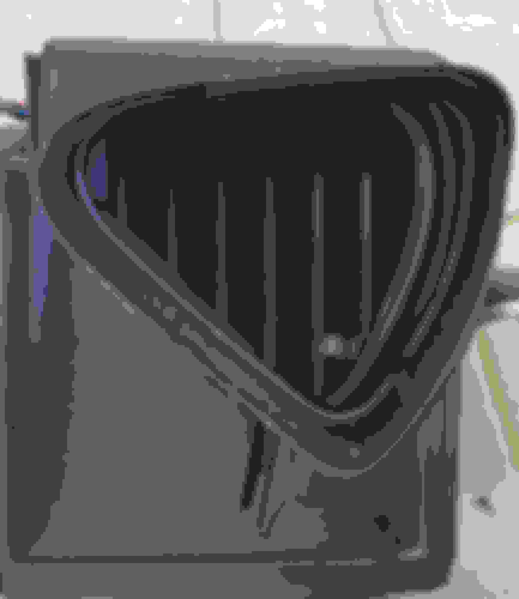
Sealing to the crash bar and under the front garnish - (still a work in progress here): The bottom bit mates with the back of the plastic crash bar. The aluminium angle sits inside/below the aluminium section of the front garnish.
This photo shows the the plastic crash bar in place, and the plastic trim shaped to fit on top of the two side pieces to hold the foam sealing strips: Aluminium tape and adhesive backed foam will provide the finishing touches.
Being a pen pusher by trade, aluminium angle in various shapes and sizes are my go-to ... This shows the front plate which will seal against the nosecone bulkhead, and the zigzag sections going back as far as the radiator sides.
Now I need to make a trip to the rubber store for the sealing strips, and the job will be pretty complete.
Valve cover completed, now with one SS scourer instead of the copper. Intercooler painted black. radiator and oil cooler ready to go in, oh wait, the nipples don't fit, order and wait for new nipples but decide to test fit with the supplied -12 nipples - one of them binds in the thread , turns out the anodising penetrated the thread of the cooler fitting, obstructing it. After a bit of to and fro, PWR offer a new cooler, hopefully here tomorrow.
In the meantime all the bushes are out of the spare suspension arms - rattlegun FTW! I have trial fitted the bushes (only) in the RUCAs, and devised a fix for the problem of the surplus hole. I don't know if others see this as an issue, but my OCD kicked in and ...
This was evident in the racecar delrin bushes, I can't remember what I did about it, but as road car, this time I needed a proper fix. The bushes need greasing (mainly to keep our debris which causes accelerated wear), but when the grease goes in, this surplus hole in the bushing housing allows the grease to escape, and potentially, debris to enter.
This shows the drilled out and tapped hole, the 8mm grub screw used to seal it, and the bushing (half):
The job almost completed - grub screw inserted, half of the bushing in place (note the rough recess for the screw):
Job done!
Note1, if you are doing this, unless you create a recess the bushes will not want to go all the way home, and this will likely cause difficulty when replacing the arms in their housings. I solved this by drilling out the hole to accommodate the grub screw with the bushes in place, drilling the bushes at the same time.
Note2, some thread locker will be in order to ensure the grub screws do not loosen and fall out.
Last edited by Gee Emm; 10-23-2018 at 07:24 AM.
Reason: spelling
Progress has been slow, but the spare arms are now sporting the PU bushes, the sleeves are stockpiled, the knuckle sleeves are being drilled for 12mm camber adjusters (Thanks for holding my hand Sean ), now I need to find my centre punch to start drilling the holes for the grease nipples.
The existing suspension is out on three corners, the fourth is well advanced. Turns out the car has been fitted with poly bushes, and so for science I tried to remove a couple of the steel pins. Fortunately I had a 5lb hammer and so I was eventually successful. So much for poly bushes, these hadn't even had any grease nipples to give some comfort that the steel pins might be rotating in the bush as they are supposed to. On closer examination, the ends of the pins look nice and shiny, I think that the pins and bushes were rigid with the bush housing, and were rotating around the bolt holding them in the chassis mount
If only that was the worst discovery! Most alarming was the state of the RH FLCA balljoint: The bolt in the bottom shock mount was loose, and had unscrewed itself about 20mm, allowing the BJ to rotate about the through bolt. The only thing stopping it from coming right out was the bottom mount of the shock absorber which was preventing it from any further unscrewing.
Also unsettling was the ease at which the bolts securing the brake callipers to the uprights came out - the rattle gun did not even activate the anvils, just 'whoosh' and they were out .
The PO was good enough to leave on the windscreen the sticker from a local suspension shop, who presumably did the bushes, and who will never be seeing any of my money.
...
In the meantime all the bushes are out of the spare suspension arms - rattlegun FTW! I have trial fitted the bushes (only) in the RUCAs, and devised a fix for the problem of the surplus hole. I don't know if others see this as an issue, but my OCD kicked in and ...
This was evident in the racecar delrin bushes, I can't remember what I did about it, but as road car, this time I needed a proper fix. The bushes need greasing (mainly to keep our debris which causes accelerated wear), but when the grease goes in, this surplus hole in the bushing housing allows the grease to escape, and potentially, debris to enter.
This shows the drilled out and tapped hole, the 8mm grub screw used to seal it, and the bushing (half):
The job almost completed - grub screw inserted, half of the bushing in place (note the rough recess for the screw):
Job done!
Note1, if you are doing this, unless you create a recess the bushes will not want to go all the way home, and this will likely cause difficulty when replacing the arms in their housings. I solved this by drilling out the hole to accommodate the grub screw with the bushes in place, drilling the bushes at the same time.
Note2, some thread locker will be in order to ensure the grub screws do not loosen and fall out.
Only because I never asked, I never knew that grease nipples could be had in 8mm thread ... so now I have a collection of straight and 90* 8mm nips to both fill the surplus hole, AND grease the bushes. They will have to wait for the new year now, but I will report on what locations these can be used.
The bottom bit mates with the back of the plastic crash bar. The aluminium angle sits inside/below the aluminium section of the front garnish.
Oops! Don't do it this way, there is a section of the nose clip that needs to fit in around the corner of the headlights, and this configuration prevents that.
I flipped the right-angle sections over, and that provided the necessary clearance easily. The centre section doesn't need any change.
Car is on the trailer, goes into the shop on Monday for a tune for the Skunk and a few other minor updates, including upgrading the Autronic to improve its performance running the alternator.
The Skunk is in and the tune tweaked, new coldside one piece piping from IC to TB. With the RB swaybar brace, the stock steel pipe was too short to go around it, so it was junked and a new one built from scratch.
My indecision over which of the three sets of shocks to use was overcome - I had an inquiry for the Xidas so they were sold, the stock PSS9s are on a mate's SE/MSM (with a bit of luck they will stay there and some cash will come my way), and the race shocks (re-valved PSS9s) and springs (750/450?) are now on the car.
The combination of the SADFab poly/bronze bushes and the race suspension (shocks on full soft) has proved to be very acceptable. The car rides firmly, no question, but lacks harshness - bumps are felt, but absorbed with no crashing and bouncing. I had been concerned about ride quality, but no longer. Likewise I had wondered if softer springs might be required, but that now seems highly unlikely.
A track day was planned, but at the last moment a leaky rear gearbox seal was found, and that was canned - I have broken one gearbox with low oil, and did not want to make it two. That has been fixed, and now I need to book another one, withdrawal symptoms are setting in ...
The exhaust manifold was leaking, so the turbo came off, and the manifold was machined. Stage 8 locknuts installed, the whole lot put back and the car was on the road before Christmas.
Then, going into town on New Year's Eve, stopped with no water. Trailered the car home, where it sat until I could get around to looking at it.
Turns out the heater water hose had come off the outlet at the back of the head.. There had been no smoke or steam at the time, so the radiator was filled, and with fingers crossed the key was turned - started immediately, idled nicely, no smoke, no overheating. Compressions are down a bit (~130), but pretty even, and it is not using water. Bullet dodged? Maybe, hopefully - time will tell. Certainly seems to have the same grunt as before, too much time driving the barge (the old Falcon wagon) resulted in a speeding ticket first time out ...
A Qmax coolant re-route is on its way, it was meant for when the head came off for the (assumed) blown HG, and the catch tank setup needs a bit of work. The rego check showed up a weep on the bottom of the bellhousing, so it looks like the gearbox has to come out and new rear main seal installed before the car is inspected for rego next year.
I have been looking closely at the radiator, and the oil cooler mounted on the back. Thinking about a dual pass crossflow rad, inlet and outlet on the cold side. That might allow me to mount my as-yet-unused oil/water heat exchanger under the crank pulley - I need to pull the undertray off, and start measuring.
Wow, two years since I updated this thread! That is what happens when life gets in the way I guess.
About the middle of last year i found water on the pax side floor, obviously coming from the heater. Replacing the heater core has been a pretty major undertaking, and with the NBs being between 17 and 24 years old those remaining ones will have either had the job done, or will soon have to have the job done. I have pulled out a number of NB dashes, but never with a view to putting them back in, so I never took a lot of notice how they were put together. As a result this was quite the learning exercise. Maybe my experience will make your heater replacement faster and smoother than mine. While I found resources on removing the dash, replacing the heater core was another matter. Note that the following is for a RHD car, I have just found a photo on here of the blower/aircon/heater assembly and the LHD has differences, they may or may not affect the following.
I looked at doing the replacement in situ, as the utube vids show, but that looked to be challenge for my aging frame working in that space, and it all looked a bit complicated with cutting the pipes, clamps and rubber hoses. So I passed on that, and as it turned out saved myself a lot of grief and frustration. This because the sealing foam used around the heater core to stop ait bypassing the heater, had bonded to both the heater core and the heater box. Getting it out of the box (without dismantling the box) was a real pain, and involved more force that I anticipated or was comfortable with. I was afraid of breaking the plastic heater box, but it survived, to my surprise. No way could I have got that out with the heater box sitting in the car. YMMV if you want to give it a go without removing the dash, but be prepared to pull the heater box if the core does not want to cooperate. Just be careful with the plastic heater box, that stuff is getting old, and is not as strong as when it left the factory, the amount of force I had to use must have gone close to breaking the plastic but I got away with it.
Lessons learned
1. Take lots of photos as you go. I removed everything I could on the dash, and then took photos showing every electrical and mechanical connection that would have to be taken apart and rejoined.
2. Remove the seats, drivers at minimum, but if you are pulling the dash remove both - lots of room, easy access. I also removed the steering wheel (that may be optional?) - that requires removing the bomb. Disconnect the battery before working on the bomb - if that goes off it will kill or maim you. Open the softtop/remove the hardtop, pretty obvious really. Pulling the dash requires removing ALL the trim around the windscreen. I just googled removing the dash, there are a number of guides for this.
3. Bag all the nuts and bolts, I used ziplok snack bags mainly, with some larger ones for bigger bits (every garage should have a full range of these on tap - they are so handy and save so much grief later on). LABEL THE BAGS! I ripped pages from a small spiral notebook, but anything will do, just label them. The advantage of the ziplok bags is that you just put the description in the bag and seal it in, no worry about smudged writing, losing the label etc.
4. I pulled all three boxes - heater, aircon, blower just so I could figure out how to get the heater and aircon to mate up. I could have left the blower alone as it turns out.
Replacing the core
The only tricky bit here is attaching the piping. The NBs use 'o' rings and finnicky little clamps to join the two pipes to the heater core (smaller versions of the v-band turbo connectors) The instructions say assemble dry, I used some red silicone - too much, wrong place. If you want to use silicone, maybe just wet the 'o' ring with silicone, put the 'o' ring on the pipe, smear a LITTLE on the 'o' ring, then assemble. Note the orientation of the clamps in the photo.
Check that the pipes sit snugly in the clamps and on their housings on the side and rear of the heater box. If they are not sitting snugly in their housing and the clamps fitting closely like they left the factory (ie there are gaps) you have done it wrong - see the photos for how they sit.
I took mine to the radiator place where I got the replacement core, where they fixed my overuse of silicone, and pressure tested the assembled heater (latter was a well spent $20 for peace of mind). You can get around all this by buying an NA heater, which is copper and comes with the pipes attached (well they did, may not now - check if you plan to take that approach.
Cleaning the joiners (the fittings that seal the gaps between the blower/aircon and aircon/heater)
Good bloody luck with that. Except that all the old foam/felt will be cactus, and has to be replaced. Paint scraper FTW, with your selection of jungle juices to remove the old adhesive. This is the worst part of the whole process.
The joiners
Easy one first - blower to aircon. 25mm felt strip might have been a bit wide, 15mm might be better and make it easier to get the bolt in. I replaced the short bolt with a longer one, but my felt was probably too bulky, get the shortest nap you can. Note, if you have taken all three out, the blower is the first one back in.
The heater box to aircon join was confusing. It seems designed for the aircon to be the last of the three to be installed - the mating aircon slides into place with the joiner already installed on the heater box. I could not see how you could assemble them in order of blower first, then aircon, then heater ( the corollary is that I can't see how just removing the heater is viable, as getting the heater back in place does not seem possible even if you can get it out in the first place). Even doing it this way I couldn't see how the felt would seal the join, the gaps were too big. I ended up using felt strips everywhere except as shown in the photo. This was where the biggest gap was, and the felt was not going to cut it. So I put the rubber strip inside the join, so that the aircon fitting slid in beside the strip of rubber. It looks like there may be a restriction of the airflow, but in reality it just reduces to the size of the heater box air entry a little earlier.
The heater side of the joiner, showing the joiner sitting on the aircon, with the rubber strips just visible (see following photo)
The rubber strips sealing the gap between the aircon and the joiner, these are installed on the aircon, not the joiner.
Reinstalling the dash
Reinstalling the dash all went pretty smoothly. The fiddly centre bolt up at the bottom of the windscreen followed the script closely. That one, and the two nuts on the base of the steering column were the main trouble spots. I rejoined all the hvac and electrical connections before attempting to bolt the dash in place, just secured it with the centre bolt and two of the door jamb bolts loosely holding it in place. I figured if I had to take it out again that would simplify things, but it all went smoothly. The one glitch I have is that the glove box lid is pushing against something, I have yet to find out what and fix it.
Pro tip #1 - for the centre bolt, replace it with one that has the unthreaded lead-in, that went in no trouble. The same would help with the four big bolts holding the base of the dash to the tabs on the tunnel. I ended up using a long pry bar to push the base of the dash forward to get the holes to align properly.
Pro tip #2 - a bit of blu tack to hold the nuts for the base of the steering column in the socket will help immensely, as will using a 1/4 socket set with a long extension, as the space around the pedals is quite limited. I now wonder if undoing the bottom mount is necessary.
Pro tip #3 - don't forget to plug the drain pipe into the aircon box.
For science, the following two photos show the difference between the ADM MX5SE (aka MSM), and the USDM MSM. Apart from the colour of the aircon box, and a slightly different alignment of the enginebay-side piping between the LHD and RHD, the differences seem to be in the joiners between the three HVAC boxes. The aircon/blower box joiner appears simpler in the LHD, with an over-centre catch compared to the RHD bolt. The RHD car has a fibre joiner linking the aircon to the heater box, the LHD car ... looks plastic, may be integral with the heater or aircon?
Thanks to Matt, from whose build thread I stole the LHD photo! Matt's build thread
It all went pretty smoothly. The fiddly centre bolt up at the bottom of the windscreen followed the script closely. That one, and the two nuts on the base of the steering column were the main trouble spots. I re-joined all the hvac and electrical connections before attempting to bolt the dash in place, figuring if I had to take it out again it would simplify things. Currently the only incomplete connection is one of the plugs for the bomb, the one that plugs into the clock spring - I figured as it was getting dark and cold, I would leave that one and attack it in the morning. I have also left the glovebox and radio for last. Likewise the centre console.
Pro tip #1 - for the centre bolt, replace it with one that has the unthreaded lead-in, that went in no trouble. The same would help with the four big bolts holding the base of the dash to the tabs on the tunnel. I ended up using a long pry bar to push the base of the dash forward to get the holes to align properly.
Pro tip #2 - a bit of blu tack to hold the nuts for the base of the steering column in the socket will help immensely, as will using a 1/4 socket set with a long extension, as the space around the pedals is quite limited. Although now I think those could have been left to slumber unmolested, in which case there would be no need to replace rge nuts, saving a lot of stuffing around.
Pro tip #3 - don't forget to plug the drain pipe into the aircon box.
The program tomorrow will be: Connect the final electrical plug; Install the cluster, connect its three plugs; Install gear lever, and rubber boot; Install the steering wheel, and the bomb; Connect the heater coolant lines, and the aircon piping, fill with coolant; and Reinstall and connect battery.
They say troubles come in threes, so I am hoping I have now cleared that hurdle and life, or motoring life anyway, will be smooth sailing from here
Trouble #1
Putting in the shocks (just had new seals put in, one was leaking), and one of the LCAs would not move - the tripod had come out of the inner housing, and there must have been a bit of movement and the alignment of the three rollers and their housing was off. Juggling the two pieces while the rubber boot was secured proved unsuccessful, partly because of the tension generated by the stretched boot, partly because obviously I couldn't see exactly what I was trying to align. Cue a messy job of taking the dust boot off, but realigning the two pieces was easy when you can see both! No photos, too messy to use the phone. The photo below shows the reassembled joint, the circle is the two tabs, and the arrow shows the over-centre lever tensioning the SS band. Those two tabs I left as the 'lever' came out, SS being notoriously fragile when bent back and forth, so I fed it back in using pliers, and then hammered the tabs down again.
Trouble #2
Got the shocks out of the carton they were shipped in, and set about re-setting the ride height. One, no problem, it was already very close to where it needed to be. The other refused to move upwards, giving every appearance of binding and stripping the thread, well down from where it needed to be. Looks like someone got so far, the thread started to tighten up, and they decided to leave it for the customer to fix. That will go back to the shop to fix on their dime. But delay for me.
Trouble #3
Having fixed the driveshaft, the next step was to install the 'good' shock. Oops! - stripped the thread in the LCA captive nut, and nothing I can do will get the bolt out that is attaching the shock to the LCA. Took the LCA down to a local engineering shop, and today they tell me the shock is out of the LCA, so that is good, now I have to find a NB RR LCA - I have one rear LCA, but it is a LR (of course!). Turns out I have LCAs for three corners, but not the one I need. I'll have to get the poly/bronze bushes out of the old one and into the new to be fully mobile, but in the short term I have a NA RR LCA which can go in while that is happening.
Trouble #4?
Dismantling the RR corner to get the hub and axle off to fix the tripod joint, I noticed that the ABS lead was under some strain - these are quite fragile, so I will be watching the ABS light in the cluster very closely on first start-up to see if there is a problem. I have spare ABS sensors, having learnt from a previous experience where a sensor went AWOL, but again not a RR. Sigh. Maybe it won't be needed, but with my current form I am not counting on it.
The car is going to run out of rego before all this is fixed, which is a manageable problem but one I was hoping to avoid.
Well, if you were wondering (as I was) how anyone could cross-thread a nut when the nut is captive and the bolt has to be passed through a locating hole, wonder no more!
It was not cross threaded, the locating cage for the nut failed, leaving the nut to spin. When I went to collect the LCA and the shock, the nut had been welded onto the arm, so no new arm, no transferring of bushes to a new arm, just bolt it all back up! That get-out-of-jail card cost me $25, cheap at twice the price.
The arm is in, the axle/hub is in, the LCA and UCA are all assembled, the brake bracket is back on and the calliper in place, just need to find my high temperature grease for the slider pins, one is quite dry. The other shock is back out, ready for the return to clean up the binding thread. Having dodged one damaged thread bullet, I don't want to do the same on an alloy shock body which may not be so amenable to a cheap and quick fix.
Tomorrow, grease the slider pin, and get the car ready to start.
Updating this thread ... engine has come out and is sitting on a tyre in the workshop, and the engineless car is now sitting on my car trailer ... because my hoist has finally taken the viagra, and has risen from the horizontal! 8) :shock:
The posts are up and bolted, I have to check the balancing cables, fill the hydraulic reservoir, put a plug on the end of the motor cable and install the arms on the carriages. I was surprised at how fast the big rotary hammer drill was able to drill the holes, I would have been happy if I could have got a bolt in each post by knock-off time, but we got them all in and torqued down.
As a bonus, I now have my two go-jacks back, as well as couple of axle stands. I really need to start selling off my collection of axle stands, I probably have two sets of the small ones, and one set of 3-tonne high lift ones surplus, I'll keep one set each of the tall and short ones. I also found a hardly used 125mm angle grinder that could go too. Maybe I should get rid the big hammer drill too, I can't see a use for that in my future ...
This week the focus will be on finishing the hoist installation, and then I will turn my attention to getting the SE engine onto the stand and lifting the head. The SE turbo together with a second turbo which was my spare will go on the chopping block, and the Kraken high mount manifold that I have been sitting on will be pressed into service ...
Hoist is up, need to fill the reservoir with hydraulic oil and put a plug on the pump motor. Installed the arms, what a bugger, a second person would have been a help but the real problem was getting the big pins in through the last of four fine tolerance holes, and it is almost impossible to sight the alignment of pin and hole. Took me a while to get the first one in, the others were easier but not by much.
The head came off the SE engine easily, not a lot to be seen. The good news is that there are no marks on the top of the No4 piston, no missing bits of metal, no lumps or holes in the cylinder wall (that I could see), the crank turns easily with no noise. So why did the rod bend? Maybe prior abuse set it up well before I bought it?
The head went back on, and the bare engine is now at Mania for checking and rebuilding with all the good gear. I am assembling all the remaining bits, and doing prep work like porting the Junk2 TB to the new (old) flat top IM. Thanks Lokiel for the tips on cleaning up the IM.
We seem to be having a rat problem here - I opened the garage door only to come literally face to face with a big rat - don't know who got the biggest shock! Poor thing, might be hungry, so I put out some more of those green pellets they like so much ...
Speaking of pests, the mud wasps are bad here, they will build muddy nests in pipes, bolt holes, anything, even a socket I left out! So I have been carefully plugging all the hose ends and the like in the car and the bits I have lying around (oil cooler, hoses, etc so that there are no nasty surprises when it all starts going back together again. As much as practical is going in plasic storage boxes with close fitting lids, very useful to protect and keep things together.
Hmm, probably one of those Ruskies fleeing conscription for the war. Well he is in a war zone here, and no mercy is shown to resident OR visiting rodents, even filigree ones

 05-02-2018, 09:25 AM


 0
0


 , turns out the anodising penetrated the thread of the cooler fitting, obstructing it. After a bit of to and fro, PWR offer a new cooler, hopefully here tomorrow.


 ), now I need to find my centre punch to start drilling the holes for the grease nipples.


 - stripped the thread in the LCA captive nut, and nothing I can do will get the bolt out that is attaching the shock to the LCA. Took the LCA down to a local engineering shop, and today they tell me the shock is out of the LCA, so that is good, now I have to find a NB RR LCA - I have one rear LCA, but it is a LR (of course!). Turns out I have LCAs for three corners, but not the one I need. I'll have to get the poly/bronze bushes out of the old one and into the new to be fully mobile, but in the short term I have a NA RR LCA which can go in while that is happening.