

Miata cooling system thread


Junior Member
Joined: Sep 2014
Posts: 216
Total Cats: 2
From: Portland (left coast)
Reply
 0
0

0

Newb
Joined: Sep 2015
Posts: 3
Total Cats: 4
Glad to help and give back a little since I have learned a lot over here in the ducting and aero threads. Let me know if you want any additional pics. I have many.
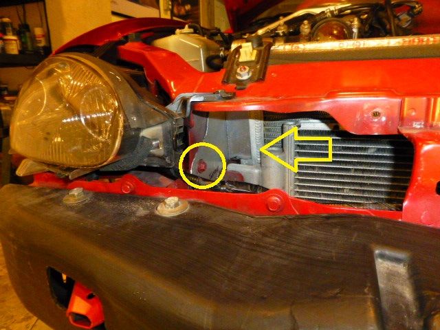
I forgot to post this pic. You can see where the side pieces attach using one of the OEM bolts (circled) and how the ~1" 90 degree bend sits against the radiator (arrow).
I forgot to post this pic. You can see where the side pieces attach using one of the OEM bolts (circled) and how the ~1" 90 degree bend sits against the radiator (arrow).
Reply
0
0


Here are some temperature loggs i made last year when i got my car running, settup is a little different than most turboed cars with a dyi coolant re-route 55mm koyo rad, w/a ic that uses the oem rad core as a water cooling heat exchanger, the car has ac installed but not running on theese logs.
First charts are on the dyno:
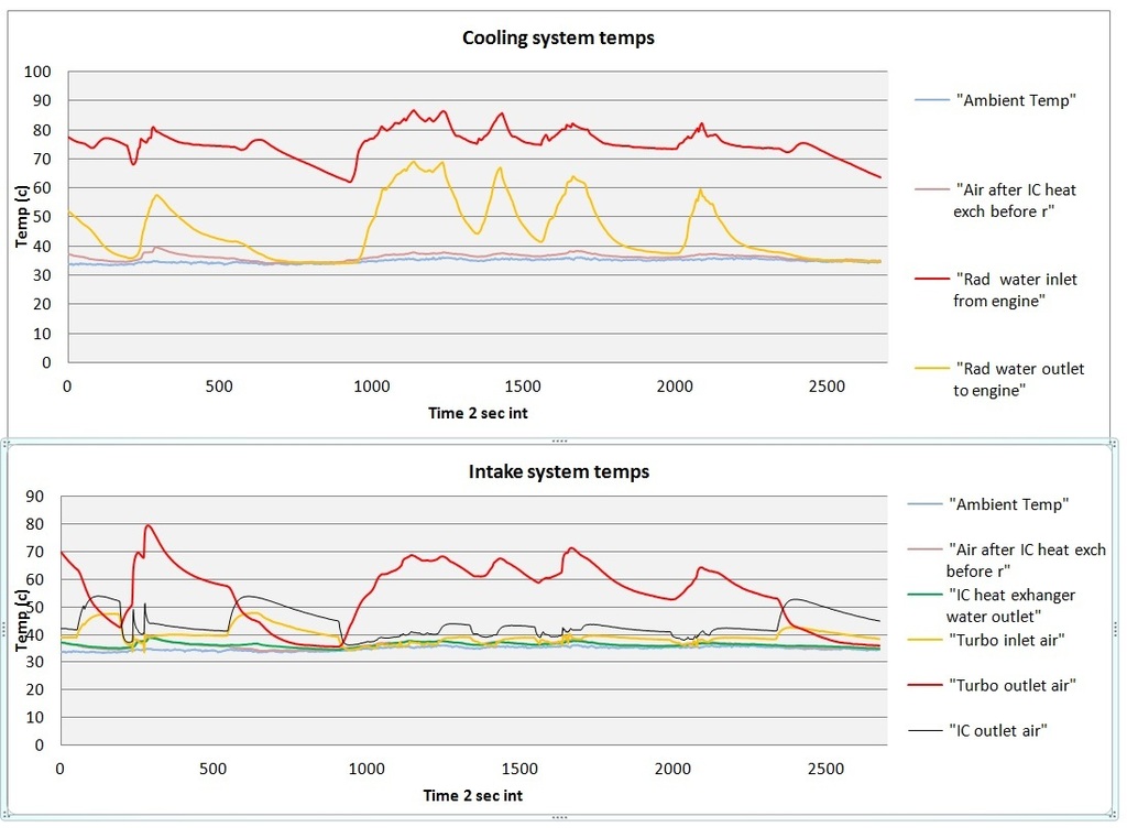
On the street for the first 1/4 chart then on the Freeway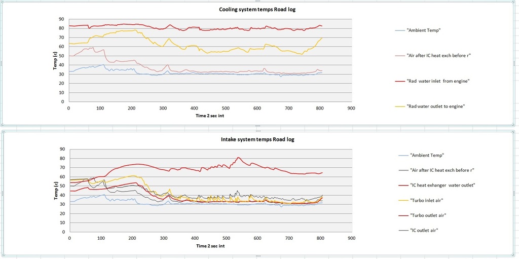
First charts are on the dyno:

On the street for the first 1/4 chart then on the Freeway

Reply
1
1

What is a correctly sized radiator for a detuned 1.6 m45 PTE car:
Supermiata Crossflow? CSF? Either one? Is the Crossflow just lighter?
Is the installed vertical envelope on either of these taller than stock? I have an over-the-radiator intercooler setup so vertical space is an issue...
- Stock pulleys
- 93 octane
- FMIC
- Ducting
- Hood Vent
- Coolant Reroute
Supermiata Crossflow? CSF? Either one? Is the Crossflow just lighter?
Is the installed vertical envelope on either of these taller than stock? I have an over-the-radiator intercooler setup so vertical space is an issue...
Reply
0
0


Junior Member
Joined: Sep 2014
Posts: 216
Total Cats: 2
From: Portland (left coast)
Anyhow, I am going to get some weather stripping or something and see if I notice a general temp drop at speed.
Reply
0
0


This would be interesting to properly instrument. My personal experience, with an NB2, is that there is airflow through that gap into the engine bay. During pollen season I would notice a lot coming through there. I ran weatherstrip along the bottom of the hood to seal it off. It's a 15 minute job to fix it. Use black rtv; the weatherstripping glue can't handle the environment.
Reply
0
0

Taping that up (and the gaps to the fenders) reduces the fluttering of the hood at speed (whatever that means).
But I have no gaps that are even close to stock after the many "adjustments" to the bumper location.
It does not have to be strong tape, using masking tape (in the right color of course) enables corner workers to open it to fight engine fire.
But I have no gaps that are even close to stock after the many "adjustments" to the bumper location.
It does not have to be strong tape, using masking tape (in the right color of course) enables corner workers to open it to fight engine fire.
Reply
0
0
Some painter's tape across that gap like Niklas mentioned would be a super-quick test.
Reply
0
0
Junior Member
Joined: Sep 2014
Posts: 216
Total Cats: 2
From: Portland (left coast)
Reply
0
0

I have a NB, and my CAI is going to the bumper (in progress now). I'll do this test and post results when I get mine off jackstands and back on the road. Any extra engine cooling is always welcomed.
Reply
0
0

Former Vendor
Joined: Dec 2007
Posts: 271
Total Cats: 11
From: Texas Hill Country
With most of the engine heat in the cylinder head, it would seem to be the place to start when trying to stay cool in a stressful environment. When asked to make something that would cruise 100 miles flat out at 140+, pumping freshly cooled water straight to the head looked like a possible answer.
We used four inlets created just below each exhaust port, a 20 gpm electric pump and a second radiator.
Thermostats at both ends. The rear Tstat and the 4 ports are routed to the 2nd rad. Coolant was allowed to mingle once inside the engine.
The 2nd rad was placed infront of the stock rad position and as high up as possible. The frontal area of #2 was 70% of #1. #1 was replaced with a 2.0" cross flow.
Ducts and baffles everywhere. On the sides, of course, but the key was a baffle from the bottom of the #2 (the add on) to the top of #1 about 5 inches behind, thus avoiding the use of the air stream twice. A panel from the lower edge of #2, going forward, served as the top of a duct beneath #2, to gather air for the #1 guy sitting in the original position. The area of this duct is about 1/5 the frontal area of rad 1.
All measurements we could apply, plus some real hard driving, suggests it worked well.
corky
Reply
0
0

Wow, that sounds quite complex. Also, sounds like this solution added 40 lbs to the nose of the car with all that extra water weight, cooling hoses, radiators, multiple thermostats, a second pump, and mounting provisions for all of this.
Definitely not the KISS approach to cooling, seems like there is now more than twice the components and connections to fail.
Definitely not the KISS approach to cooling, seems like there is now more than twice the components and connections to fail.
Reply
0
0
Interesting. I know Texas is a big state but I'm curious as to where 140 for 100 can be done.
Also I'm curious as to flow within the engine now. Stock, we have one high pressure source (the water pump); from there everything flows "downhill", so to speak, to the radiator, into one low-pressure intake (the water pump). No eddies are possible. With this configuration there are now five high pressure sources, and two low pressure intakes. How do you prevent / know you don't have any stagnant high-temp eddies?
Was the 140 for 100 attempted and failed previously with a conventional (possibly supersized) cooling approach?
Reply
0
0


