Alternator Control. Dead nailed. MS3 / MS3-Pro / MSPNP-Pro
 06-23-2014, 10:18 AM
#61
Supporting Vendor


Thread Starter
iTrader: (33)
Join Date: Jul 2006
Location: atlanta-ish
Posts: 12,659
Total Cats: 134
This should work correctly. Test on a stim first. With the pullup installed, test for voltage on your Nitrous 1 output. With the charge setpoint below current system voltage, you should see 0V on your meter. With charge setpoint above system voltage, you should read 5V. If you read the opposite, invert the logic, which is what I think is going on here.


Reply
 0
0

0
06-23-2014, 09:14 PM
#62

This should work correctly. Test on a stim first. With the pullup installed, test for voltage on your Nitrous 1 output. With the charge setpoint below current system voltage, you should see 0V on your meter. With charge setpoint above system voltage, you should read 5V. If you read the opposite, invert the logic, which is what I think is going on here.
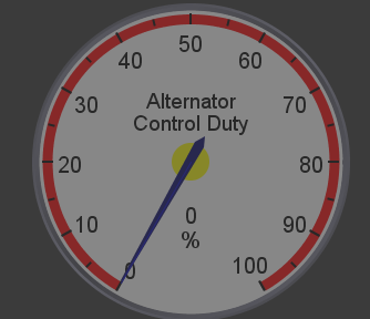
Didn't test it on the stim, but I didn't notice this:
I don't believe MS is ever even trying to charge the battery. The alternator control duty cycle never leaves 0.
Reply
0
0
06-23-2014, 11:28 PM
#63
Just to be clear and double check myself, is the following acceptable?
M30 - Generator Field Control (main board idle valve)
M32 - Battery Light (main board injector 1)
I see that main board idle valve lists max current at .8Amps. Is that sufficient for the field control or do I need to use my only remaining PWM output (VVT)?
Also, can I get away with using the IAC1 or IAC2 circuits? What would I need to do to make that work?
Attached you will find my current inputs/outputs file.
Reply
0
0
06-24-2014, 06:52 AM
#64
Senior Member

Join Date: Nov 2007
Location: Belgium
Posts: 999
Total Cats: 73
There must be a page describing the output signal of each pin, but I can find it. I wish I could point you to it Stephen. Since the IACs provide 12V, I suppose a PNP behind it must work, but what do I know and it's not in the manuals.
Ben, don't take this as criticism towards you guys. I know you don't make the manuals and are not responsable for them. I genuinely do not now where to find the information on what type of signal each pin outputs. And trust me, I do read the manuals. I practically know the the schematics by heart by now, but still find it a nightmare to find information. Must be my lack of brains.
I do know the IACs are for a stepper valve and supply 12V, the LEDs supply 5V, but no clue on JS4,5,10,11 etc.
Since the IACs can do PWM Boost, I figured they were PWM outputs, needing the configuration you mentioned, although I did find it odd. But then again, nothing in the manuals about this, only information scattered around on various forums, in various topics.
You can't say that all that information is readily available on line, it simply is not.
Reply
0
0
06-24-2014, 09:03 AM
#65
Boost Czar

iTrader: (62)
Join Date: May 2005
Location: Chantilly, VA
Posts: 79,493
Total Cats: 4,080
When I was going through msextra, and trying to find ANY docs on how to wire the alt. control, it was suggested you use a 330-470ohm resistor. 1K might be a touch too much.
I feel like a lot of confusion would be removed if someone just posted EXACTLY how to wire it. Ben, you suggest that they should wire it "like in [your] posts" but you don't ever really outline how to wire it, like at all.
Like why not something like this:
99-00
1O - Nitrous 1 out (330ohm pull-up to 5v)
1T - I dunno cause no one has ever suggested what you need to wire alt sense to and I spent over an hour looking for documentation on the alternator control and was unable to find any, only a few posts from back in Jan where Ken was talking about first developing the function...
On the pull-up note, would not using Spark e-f-g-h (Normal) not make more sense since it already outputs 0-5v and you don't need to do additional wiring?
Frank, almost all the outputs on the mainboard need additional circuits to work correctly. you'd need to build a pwm circuit on the proto area to use JS0.
Reply
0
0
06-24-2014, 09:20 AM
#67
Boost Czar
iTrader: (62)
Join Date: May 2005
Location: Chantilly, VA
Posts: 79,493
Total Cats: 4,080
what's the base voltage of the stim? I use a power supply on my stim to increase/decrease the system voltage in order to test alternator functions.
I'm assuming your stim's voltage is under 15v? That would be a "trying to charge" condition, since 0% DC would be 5v. If you metered nitrous 1, you'd see 5v. You need to be able to increase the system voltage about the charge point. So alter the target voltage to be below/above the system voltage to test.
looking again, the suggestion to go from 1K to 330ohm was because he couldn't command more than 13v to charge. So the value shouldn't matter, since it's not about amperage draw.
Reply
0
0
06-24-2014, 09:25 AM
#68
Though you are correct, I hadn't thought about the fact that maybe 100% duty is not charging.

Reply
0
0
 06-24-2014, 02:00 PM
#72
Ben, don't take this as criticism towards you guys. I know you don't make the manuals and are not responsable for them. I genuinely do not now where to find the information on what type of signal each pin outputs. And trust me, I do read the manuals. I practically know the the schematics by heart by now, but still find it a nightmare to find information. Must be my lack of brains.
I know this isn't the right forum for it but it is an example of how confusing it can be. When I built my MS3, I heard people use words like "flyback", "pull-up" etc without knowing exactly what it meant.
I am not an electronic wiz but I do understand the different types of functions that each "signal" can provide.
Toggle (ground = on)
Toggle (12v,5v etc = on)
PWM OUT
etcetera.
Some inputs and outputs can be converted to different uses, right? How does one go about doing this? For example, at the bottom of the link I provided there is a table called "MS3 pin usage chart."
For example,
"Fidle" : Megasuirt pin #30
Max current 0.8A
Typical MS2 usage: PWM Idle Valve
Typical MS3 usage: Spare output
Alternative functions: Datalog LED, Boost Control PWM Output, Generic Output
This page covers the wiring for PWM mid current outputs, but it doesn't include MS pin #30 in the list. What else is involved in using the above referenced pin as a PWM out? Is there anything that I need to know so I don't hurt anything?
It's stuff like that. I can follow wiring diagrams, I generally understand schematics, but when it comes to customization I am pretty clueless.
Reply
0
0
06-24-2014, 02:29 PM
#73
Boost Czar
iTrader: (62)
Join Date: May 2005
Location: Chantilly, VA
Posts: 79,493
Total Cats: 4,080
This page covers the wiring for PWM mid current outputs, but it doesn't include MS pin #30 in the list. What else is involved in using the above referenced pin as a PWM out? Is there anything that I need to know so I don't hurt anything?
that's because that page is specifically discussing the Expander outputs.
im sure anyone that's build a MS1 or MS2 or non-expander MS3 knows that you must build a PWM circuit using a TIP122 in order to use "pin 30" as a PWM output to drive things like the idle valve. (the schematics/docs tell you this as well)
Reply
0
0
06-25-2014, 10:32 AM
#75
Supporting Vendor
Join Date: Sep 2006
Posts: 2,332
Total Cats: 67
Reply
0
0
06-25-2014, 07:05 PM
#76
Senior Member
Join Date: Nov 2007
Location: Belgium
Posts: 999
Total Cats: 73
Not at all. I practically know that table by heart. I'd like to see a page that describes the output signal of each pin in each possible mode (input - output), not its function.
For instance, what signal do JS10 and JS11 provide in output mode (tacho out, generic out, boost pwm out)? Is it a ground? 5V? 12V?
For instance, what signal do JS10 and JS11 provide in output mode (tacho out, generic out, boost pwm out)? Is it a ground? 5V? 12V?
Reply
0
0
 06-30-2014, 11:07 AM
#78
Supporting Vendor
Thread Starter
iTrader: (33)
Join Date: Jul 2006
Location: atlanta-ish
Posts: 12,659
Total Cats: 134
When I was going through msextra, and trying to find ANY docs on how to wire the alt. control, it was suggested you use a 330-470ohm resistor. 1K might be a touch too much.
I feel like a lot of confusion would be removed if someone just posted EXACTLY how to wire it. Ben, you suggest that they should wire it "like in [your] posts" but you don't ever really outline how to wire it, like at all.
Like why not something like this:
99-00
1O - Nitrous 1 out (330ohm pull-up to 5v)
1T - I dunno cause no one has ever suggested what you need to wire alt sense to and I spent over an hour looking for documentation on the alternator control and was unable to find any, only a few posts from back in Jan where Ken was talking about first developing the function...
On the pull-up note, would not using Spark e-f-g-h (Normal) not make more sense since it already outputs 0-5v and you don't need to do additional wiring?
The Mazda diagram is kind of confusing. 99/00:
Alternator field is 1O
Alt sense is 1T
01/05:
field is D4
sense is E27
Where D is the 24 pin plug and E is the 31 pin plug
I wouldn't use a spark output as the 5V source, unless you add a transistor buffer circuit.
Reply
0
0
07-02-2014, 11:25 AM
#79
Supporting Vendor
Join Date: Sep 2006
Posts: 2,332
Total Cats: 67
Not at all. I practically know that table by heart. I'd like to see a page that describes the output signal of each pin in each possible mode (input - output), not its function.
For instance, what signal do JS10 and JS11 provide in output mode (tacho out, generic out, boost pwm out)? Is it a ground? 5V? 12V?
For instance, what signal do JS10 and JS11 provide in output mode (tacho out, generic out, boost pwm out)? Is it a ground? 5V? 12V?
Reply
0
0


