
Trackspeed's '02SE "Acamas" - EFR6758, TSE motor, 500whp or bust


So ideally, the charge voltage at the battery will be ~14VDC. As the battery voltage approaches this value, the charge current drops. The resistance of the wire from the alternator reference at the Main Relay box actually may be beneficial to some degree, it will serve as a current limiter that the battery reacts against. The instantaneous voltage at the battery terminals is static (ignoring the battery internal resistance) regardless of load. The battery stabilizes the system voltage in this way. The direction of the current at the battery terminal is dynamic with load in this scenario. If the alternator voltage minus the losses (both resistive and otherwise) across the source network to the battery is LOWER than the battery voltage, the current will flow out of the battery. If it is HIGHER than the battery voltage the current will flow into the battery. The fuel pump described in this thread may approach a 30A load, which is significant. This will theoretically result in the said voltage being LOWER more frequently, which will result in a discharge cycle. Couple this with the reverse temperature coefficient of the reference in my alternator (at least), and you get alternator voltages of ~13.5 volts at temperature, and battery voltages in the high to mid 12's. While I haven't measured the current into the battery under these conditions, I would venture to guess that they are nearly zero, so not really charging, not really discharging.
Reply
 0
0

0
Reply
0
0

Joined: Apr 2014
Posts: 18,643
Total Cats: 1,870
From: Beaverton, USA
If I were to go as far as run 10awg wire back to the fusebox from the fuel pump I would probably just run a pair of like 4awg welding cables or whatever from battery to engine bay. all of the voltages erywhur
Reply
0
0
Reply
0
0

Thread Starter
Joined: Nov 2006
Posts: 15,442
Total Cats: 2,106
From: Sunnyvale, CA
If it poses a problem it's easy enough to route the fuel pump lead to the alternator or fusebox at a later date. I assume the logic here is that the charge/discharge cycles will decrease battery life?
The DW300 at ~85psi draws ~13.5A. The Walbro 450 at 85psi draws ~18.9A.
The DW300 at ~85psi draws ~13.5A. The Walbro 450 at 85psi draws ~18.9A.
Reply
0
0
Reply
0
0

If it poses a problem it's easy enough to route the fuel pump lead to the alternator or fusebox at a later date. I assume the logic here is that the charge/discharge cycles will decrease battery life?
The DW300 at ~85psi draws ~13.5A. The Walbro 450 at 85psi draws ~18.9A.
The DW300 at ~85psi draws ~13.5A. The Walbro 450 at 85psi draws ~18.9A.
Reply
0
0

Senior Member
Joined: May 2015
Posts: 514
Total Cats: -10
From: Grand Rapids, MI
 I had an adapter to attach to the factory FPR flange, but decided to just cut it off instead for simplicity.
Reply
0
0

Joined: Sep 2010
Posts: 8,154
Total Cats: 1,093
From: Lake Forest, CA
Ships tomorrow
Last edited by shuiend; Dec 21, 2016 at 02:42 PM.
Reply
2
2


I'd be interested in some wiring/relay kit too maybe depending on what all it is. Already have the DW300 and Fuelab FPR. Need to read through this and a few other threads again a little more carefully but need to start planning out my fuel system for my TSE EFR install. It's great to read up on what you guys are doing.
Reply
0
0

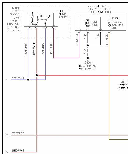
Is fudging with the bulkhead required? I've heard the short run of wiring from the bulkhead connector to the pump itself wasn't long enough to require the increase in gauge.
Reply
0
0
Joined: Apr 2014
Posts: 18,643
Total Cats: 1,870
From: Beaverton, USA
As stated earlier. Its not enough to cause a significant drop. But some of use are worry warts and I don't like the idea of 20Amps going through the stock 26 year old connector on my pump.
Reply
0
0

Elite Member
Joined: Jul 2005
Posts: 6,420
Total Cats: 84

Reply
-1
-1
Joined: Apr 2014
Posts: 18,643
Total Cats: 1,870
From: Beaverton, USA
Not if you want to do PWM. Or have less voltage drop. Or not have a toasty relay under the dash running lots of current through it. Also that is a lot further to run a wire than to the battery.
Reply
0
0
All-round "Good Guy"

Joined: Dec 2009
Posts: 1,036
Total Cats: 266
From: Brisbane, AUSTRALIA

Based on the slim harness, it doesn't look like it.
I'm planning to re-make mine to make the lead to the OEM harness connector longer so that it's not all stuffed between the motor and firewall.
Originally I used a single 0.47uF capacitor on each of the 2 harnesses (coils 1&4 and 2&3) since it was the largest I could find on the day I made them but didn't include the 0.001uF capacitor since I'd read that few people included it in their harness:

- the capacitor is clad in clear heatshrink, so that I can see if/when it leaks, and zip-tied to the harness
As you said, making harnesses is time consuming and if you haven't used these capacitors that's good enough for me not to use them either since it makes the harness easier and tidier to make.
Reply
0
0
Elite Member
Joined: Jul 2005
Posts: 6,420
Total Cats: 84
Hang on that's not right.
10 ft of 8 gauge is 6 milliohms.
The 20A fuel pump will cause 0.12 V of drop. Not worth worrying about.
Wire it to the battery using 14 gauge.
Be sure to fuse it with a 30A fuse, sitting near the battery.
10 ft of 8 gauge is 6 milliohms.
The 20A fuel pump will cause 0.12 V of drop. Not worth worrying about.
Wire it to the battery using 14 gauge.
Be sure to fuse it with a 30A fuse, sitting near the battery.
Reply
0
0
Thread Starter
Joined: Nov 2006
Posts: 15,442
Total Cats: 2,106
From: Sunnyvale, CA
The run from the battery to the pump following reasonable paths (along existing loom paths and through OEM grommet) ended up being nearly 8ft of wire, which will be 0.21v of drop with 10awg. 14awg would be 0.53v at 13A (DW300) and 0.81v at 20A (Walbro450).
Reply
0
0


