

3d printed intake for N/A NA miatas


Nothing is impossubruueeee!
Got it to work. Easier said then done. I had to basically reverse engineer and recreate the geometry from the IGS surface model. I don't have access to photobucket to share the pics at the moment but I'll post them here later today.
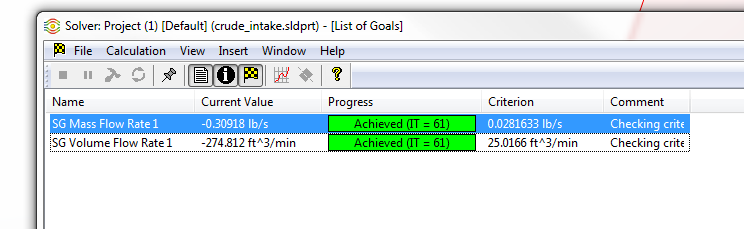
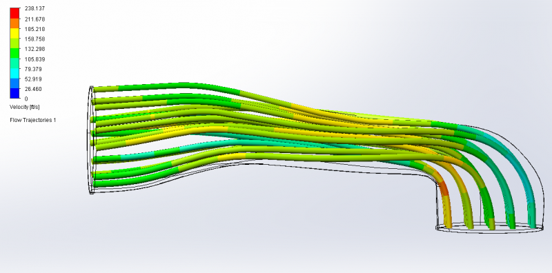
Overall it looked good. 275 cfm at .2 psi pressure drop. No major areas of choking.
Got it to work. Easier said then done. I had to basically reverse engineer and recreate the geometry from the IGS surface model. I don't have access to photobucket to share the pics at the moment but I'll post them here later today.
Overall it looked good. 275 cfm at .2 psi pressure drop. No major areas of choking.
Reply
 2
2

2
Here are the pics. Usually I figure out what the max CFM is for a given HP then set a pressure drop across the tube to achieve that flow. In this case 0.2 psi differential for 275 cfm. Then I look at the velocity and you want linear flow (no swirl) and no major velocity changes. Where it makes the 90 bend is the area you want to focus on but there's not much you can do there do to geometry constraints most likely. Typically I will iterate the design and run the CFD same mesh size and boundary conditions and compare to see how much CFM I gained, or lost, due to the changes.
Seeing how your velocity through the flattened section is pretty constant you maintained a decently constant cross sectional area.
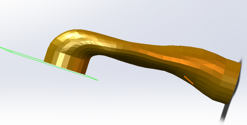
The Original
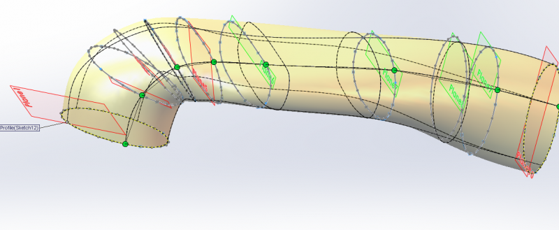
Sliced and lofted back to a solid body
The results:
Velocity plot top view
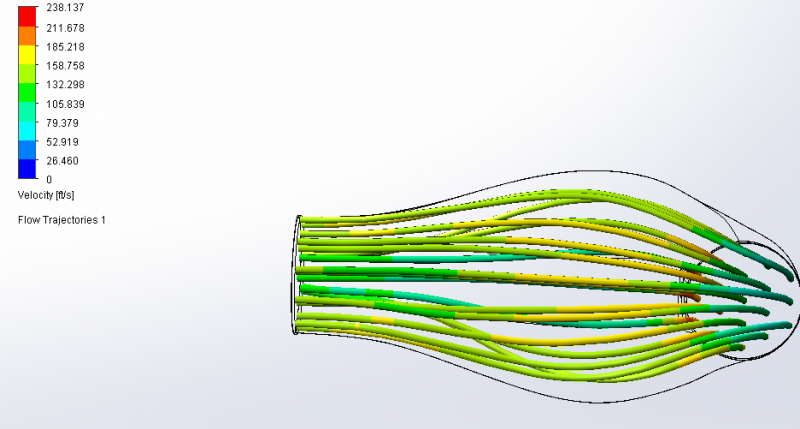
Velocity plot side view
Seeing how your velocity through the flattened section is pretty constant you maintained a decently constant cross sectional area.
The Original
Sliced and lofted back to a solid body
The results:
Velocity plot top view
Velocity plot side view
Reply
1
1

Thread Starter
Joined: Jul 2012
Posts: 792
Total Cats: 143
From: durham NC
Expensive Pegasus racing foil didn't do anything- not really surprising that stickers couldn't fix it.
Edit:
Actually maybe not. The thing still heat soaks bad when sitting still but my logs from driving today show an average 8 degrees above ambient at speed.
Edit:
Actually maybe not. The thing still heat soaks bad when sitting still but my logs from driving today show an average 8 degrees above ambient at speed.
Reply
0
0

this was a very common issue with MS users early on, we all started putting our AIT sensors just after the IC...I suggest you move yours just behind the filter.
Reply
0
0
Thread Starter
Joined: Jul 2012
Posts: 792
Total Cats: 143
From: durham NC
I did a test layup using one of the older prototypes. I don't have vacuum bagging equipment yet so I did a hacky compression wrap with electrical tape. Aside from excess resin puddling into streaks on the surface, it worked really well. I used a single layer of 15oz carbon biaxial sleeve and the part is super strong now- I was able to stand on it without breaking it.
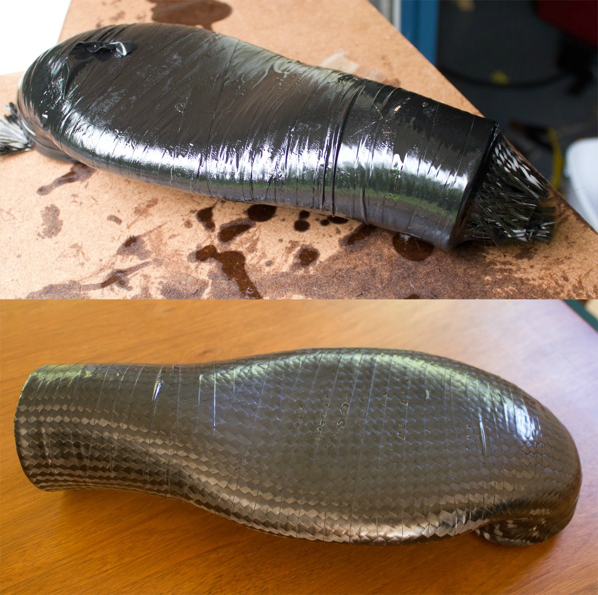
I have a thinner walled ABS print on it's way so that the final exterior dimensions will be the same with the added carbon layer. Also, if I wanted this to look nice I could sand down the excess epoxy, fill in the couple of pin holes, and then polish it up. More than likely it is going to get foil wrapped so I won't bother.
I have a thinner walled ABS print on it's way so that the final exterior dimensions will be the same with the added carbon layer. Also, if I wanted this to look nice I could sand down the excess epoxy, fill in the couple of pin holes, and then polish it up. More than likely it is going to get foil wrapped so I won't bother.
Reply
0
0
Thread Starter
Joined: Jul 2012
Posts: 792
Total Cats: 143
From: durham NC
I came up with a reliable way to form seamless carbon tubes- I want to try something like this on the intake duct using poured silicone.
For this crossover I will drill a hole for the bung, use structural epoxy to fit it into place, and then layup another layer of carbon fiber overtop.
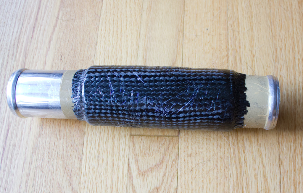
For this crossover I will drill a hole for the bung, use structural epoxy to fit it into place, and then layup another layer of carbon fiber overtop.
Reply
1
1
Thread Starter
Joined: Jul 2012
Posts: 792
Total Cats: 143
From: durham NC
I designed the air intake heat shield and I am going to have the tool 3d printed soon. My plan is to use kevlar and uni-directional carbon for the clamp ring and a normal carbon weave for the rest of the part. The piece is designed to slip fit over the outside of the filter and the hose clamp with fit overtop holding it all together. I will mount a go pro and drive the car at speed to make sure that the filter doesn't flex back and bang the radiator.
I also worked out a way to cheaply make small runs of the intake duct in carbon fiber without needing to sacrifice a $80 3d print each time. I am going to cast candle making wax into a plug, wet layup overtop, and then vacuum bag it all together.
I also worked out a way to cheaply make small runs of the intake duct in carbon fiber without needing to sacrifice a $80 3d print each time. I am going to cast candle making wax into a plug, wet layup overtop, and then vacuum bag it all together.
Reply
0
0
Thread Starter
Joined: Jul 2012
Posts: 792
Total Cats: 143
From: durham NC
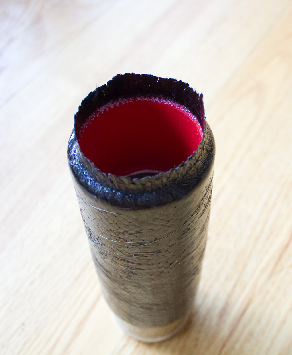
This is my attempt at a crossover tube to prevent sensor heat soak. There is a 1.75mm air gap between the tubes and I will lay up carbon onto the the 3d printed piece and use that to box the air around the sensor. If IAT sensors heat soak is caused by air already inside the intake this won't do much- If it is heat from the block or radiator making its way into the intake as the car sits this will help a lot. The top of the plastic section is big enough to fit a socket for changing the sensor out and will get sealed off with foil.
Last edited by asmasm; Jul 13, 2014 at 07:25 PM.
Reply
1
1
Thread Starter
Joined: Jul 2012
Posts: 792
Total Cats: 143
From: durham NC
Yeah, me too. It was a lot of effort (but only about $40 in materials) and there is a good chance it won't do ****. I think on a more normal intake design where there is a longer crossover tube and you could extend this concept to be 15-20" it would work better.
Reply
0
0
I have the feeling it will more so trap heat rather than block it. IMO a better thing to do is to run a fan that will pull ambient air pointed directly at the sensor that turns on every 5 minutes for couple minutes for like 2 hours after turning off the engine. A simple 60-80mm fan should be more than enough to get rid of sensor heat that wont drain the battery after running for 2 hours.
Reply
0
0


Thread Starter
Joined: Jul 2012
Posts: 792
Total Cats: 143
From: durham NC
I made a quick webpage for the intake so people wouldn't have to read this entire thread. I typed out all the content in dreamweaver so I am sure there are tons of errors I am yet to see. I also uploaded the final version of the model in stl format, the inner surface and an FBX file so people can make changes, and I included the 3d scan of the expanding foam pour.
Intake Page
Intake Page
Reply
0
0


