

New Wing to Test


Mulsanne's Corner: Race Car Engineering Le Mans 2011
Bottom of the page. It was a regulatory work around more than an advance in aerodynamics.
Bottom of the page. It was a regulatory work around more than an advance in aerodynamics.
Reply
 0
0

0

Mulsanne's Corner: Race Car Engineering Le Mans 2011
Bottom of the page. It was a regulatory work around more than an advance in aerodynamics.
Bottom of the page. It was a regulatory work around more than an advance in aerodynamics.
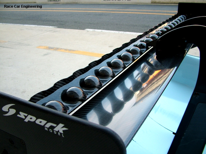
>>A few weeks ago we posted a really interesting image, taken at the Le Mans Test Day, of Oak Racing's rear wing flap. We had a think, talked to a bunch of people, and have the answer as to what's going on there. This was the process:
Since the 2004 LMP1 regulation changes (and even before that with the LMP900 regulations), the ACO have mandated a gurney on the rear wing flap that is 90 degrees to the plane connecting the top of the wing to the trailing edge (see FIA Drawing 258-8 in Article 3.6.3 of the ACO regulations). Initially the mandated height was 15 mm, then in 2009 this was raised to 20 mm. 2011 saw the introduction of engine capacity reductions for LMP1 resulting in the loss of about 100 horsepower for the top diesel LMPs. This has led to a trend shift in aerodynamics development from pure downforce generation to drag reduction and efficiency first, downforce second.
While it is only a small detail when looking at the entire car, the mandatory 20 mm gurney is even more of a liability than in years past. But there's precious little that can be done about it...or is there?
First seen at the 2011 Le Mans test day, Oak Racing have hit upon a clever design execution that maneuvers around the gurney regulation. Ultimately the concept is a regulatory work around and nothing more, though more on the specifics in a moment. But getting to this conclusion was fraught at first. Initially it was suggested that the protuberances were designed with pure aerodynamics in mind; discussions were rampant about the bumps acting as vortex generators. There was even mention the bumps were utilizing an aerodynamic concept seen in nature and on of all things, whales. Yes, the giant mammal kind.
Apparently scientists have always been puzzled about whale�s agility given their size. And when researched, they took note of bumps on the leading edge of whale fins. They came to the conclusion the bumps help reduce span wise leading edge flow migration and locally better organized the water flow leading to a much more efficient fin (or wing). Hey, don�t shoot the messenger, I�m just repeating what I read.
I must admit I wasn�t convinced that was the cue Oak Racing had taken, though admittedly I had nothing else. Apparently the research is three years old, and lacking direct access to their numbers, one has to utilize the school of observation. And the best place to do that is to observe what�s going on in F1, the �bleeding� edge of motorsports aerodynamics. No one has, to my knowledge, shown up on a F1 grid recently with a wing that had bumps or similar on the leading edge.
At about this time I received an email from a former colleague who is now with an F1 effort, asking me, of all people, what I knew about the Oak Racing wing flap. Lacking anything else, I repeated the rather weak-sauce story about the whales. Yeah, I did. But the fortunate thing for me was that in the email ping-pong the answer shook out.
Ultimately it's pretty simple. But first you have to think about the wing in cross section. The mandatory 20 mm gurney has to be perpendicular to the line connecting the top of the wing to the trailing edge. But Oak Racing has increased the height of the wing opposite the �conventional� cross section in an alternating pattern (the bumps). And when you connect the top of the bump to the trailing edge, the perpendicular gurney is leaned back relative to the conventional section (approximately 30 degrees in our example). And as the top of the wing is relatively insensitive (note that the important low pressure side is untouched), any loss from the bumps is more than made up for by the alternating gurney angle reduction.
Throughout all of this I was finally able to reach Oak Racing's Technical Director Christophe Chapelain. Chapelain immediately confirmed the concept was indeed a rules work around driven by the desire to reduce drag. Says Chapelain, �The gurney is one of the most important piece for the drag. It (the idea) came from a sort of brain storming.� Team aerodynamicist Nicolas Clemencon utilized CFD to flesh out the concept and followed that up with wind tunnel testing at RUAG in Switzerland to validate. The result, according to Chapelain, is the same level of downforce for slightly less drag. Chapelain also indicates that there is some negative interaction from the bumps (flow separations), but not enough to take away from the positives. The wing is also just on the edge of improved L/D; the flap wasn't used at Spa because at higher downforce levels it's more efficient to use a standard flap without any bumps.
And Oak Racing's concept hasn't been dismissed outright and rival outfits are already mulling the possibilities. �Well, it depends on how big the negative effect of the flap top surface modification...I will know more after trying it, possibly in a nicer way,� this according to one aerodynamicist for a current LMP project. One wonders if there's been enough time between the Le Man test and the race...we'll see soon enough!
I was expecting to hear mention of the whale tubulars, but those are supposed to be on the leading edge.
Reply
0
0


http://clubroadster.net/vb_forum/89-...thread-19.html
The final one is actually Version 3 of a process of redoing the diffuser several times over a two week span. Post # 566 is the first version, progressing to post # 594 on page 20 with the final version that you see now.
-Ryan

Reply
0
0

Measured with a level sitting on the wing or estimated CL to CL? Do you think this is an ideal range or should I pursue something wider and/or shifted? 
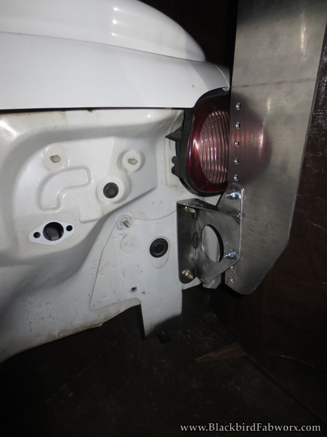
Think I'm going to make my own mounts - combination of your and the FM designs and using my wider mounting points. Rear view be like this:
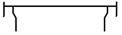
Think I'm going to make my own mounts - combination of your and the FM designs and using my wider mounting points. Rear view be like this:
Reply
0
0
Measured with a level sitting on the wing or estimated CL to CL? Do you think this is an ideal range or should I pursue something wider and/or shifted?
Think I'm going to make my own mounts - combination of your and the FM designs and using my wider mounting points. Rear view be like this:
Think I'm going to make my own mounts - combination of your and the FM designs and using my wider mounting points. Rear view be like this:
After playing with the COT airfoil shape in the flow program linked earlier in this thread, it looks like it produces good downforce up to about 12* with a pretty linear increase in drag up to that point, and as the angle increases beyond that, drag begins to ramp up quickly.
Of course, angle of attack is measured relative to horizontal - just because that's easy to measure. But, the wing isn't getting completely horizontally-moving air, even when mounted nice and high/far back. Much of the wing is getting slightly downward-flowing air that is coming over the roof, so the real angle of attack of the airfoil relative to the direction of airflow is a steeper angle than our relative aoa measurement from horizontal. We'll never know exactly what angle that air is hitting the wing at, so it's all just a game of getting things in the right ballpark and tweaking according to the feel of the car. But, I like the range of adjustment I have - my almost maxed out 7* relative to horizontal, with air moving downward at a 5* angle (totally an arbitrary estimate) puts the airfoil at 12* to the direction of flow, so I think this range is good for all the angle you'd want.
I have yet to begin real-world testing, and front aero is being reworked soon to match the increased rear aero, and until that is done I foresee running the wing at near-horizontal.
-Ryan
Reply
0
0


Reply
0
0
The files are at the fab shop, we're just waiting for the prototypes. We've got both NA and NB ones coming this time. The NB trunk lid has sides that are less parallel than the NA, so there's a bigger difference than just bending the bottom edge.
CNC fabrication means very consistent parts, but it takes longer to set up than just banging one or two out in your home garage We don't have a big industrial laser here (good thing, too, or there would be weekly Goldfinger reenactments) so we're having to deal with a longer turnaround time as we wait for parts from Paco.
I'm just about ready to open the group buy so we can get this underway. Once the prototypes are confirmed, we'll go into production.
CNC fabrication means very consistent parts, but it takes longer to set up than just banging one or two out in your home garage
We don't have a big industrial laser here (good thing, too, or there would be weekly Goldfinger reenactments) so we're having to deal with a longer turnaround time as we wait for parts from Paco.I'm just about ready to open the group buy so we can get this underway. Once the prototypes are confirmed, we'll go into production.
Reply
0
0

Newb
Joined: Mar 2011
Posts: 20
Total Cats: 9
So this is where all the cool kids are hanging out. I'm going to have to look into this COT wing. I know jpreston was running it at nationals and talking to me and a friend about it afterwards. I'm just not around the computer enough to keep an eye on eBay auctions. Womp Womp.
Reply
1
1
Newb
Joined: Mar 2011
Posts: 20
Total Cats: 9
Reply
0
0

Senior Member
Joined: Dec 2012
Posts: 624
Total Cats: 81
From: Charlotte, NC
So this is where all the cool kids are hanging out. I'm going to have to look into this COT wing. I know jpreston was running it at nationals and talking to me and a friend about it afterwards. I'm just not around the computer enough to keep an eye on eBay auctions. Womp Womp.
Reply
0
0
Newb
Joined: Mar 2011
Posts: 20
Total Cats: 9
Try pinging Bryan at Circle Track Warehouse in Mooresville, NC. I'm not sure if he has any left in stock, but I paid about $100 less for mine through him than most of the "OMG you got a screaming deal" prices I see people paying for them online. Mine was off a DEI wind tunnel car and already had a gurney flap on the rear.
Reply
0
0

Senior Member
Joined: Oct 2011
Posts: 842
Total Cats: 415
From: Northridge, CA
I bought a COT wing as well.
It'll be interesting experimenting with it on my car since the aero is completely different of that of a normal Miata.
It'll be interesting experimenting with it on my car since the aero is completely different of that of a normal Miata.
Last edited by Blackbird; Jan 26, 2013 at 03:04 AM.
Reply
0
0

In theory you shouldn't have mount the wing as high to get it into cleaner air. Your aero pod should play an interesting part though.
Reply
0
0
Senior Member
Joined: Oct 2011
Posts: 842
Total Cats: 415
From: Northridge, CA
I actually have a new pod that I made just a few days ago to replace the prototype piece that was on the car.
I'll be making a set of simple crude height adjustable mounts for the wing to test for vertical placement, once I have a better idea where I want it I'll make my permanent mounts.
I'll be making a set of simple crude height adjustable mounts for the wing to test for vertical placement, once I have a better idea where I want it I'll make my permanent mounts.
Last edited by Blackbird; Jan 26, 2013 at 10:04 PM. Reason: typo
Reply
0
0
Alu or steel? Is that stiff enough to avoid flexing side to side?
I am considering doing something similar, except wrapping underneath and up, mounting to the sides of the bumper supports so as to not affect my bodywork. Still a prissy street car and all.
I am considering doing something similar, except wrapping underneath and up, mounting to the sides of the bumper supports so as to not affect my bodywork. Still a prissy street car and all.
Reply
0
0


