
Trackspeed's '02SE "Acamas" - EFR6758, TSE motor, 500whp or bust


I could be wrong on the V drop, used the first calculator google popped with. Also could be wrong on the size of that wire.
Last edited by Ted75zcar; Dec 23, 2016 at 12:12 AM.
Reply
 0
0

0

Elite Member
Joined: Jul 2005
Posts: 6,420
Total Cats: 84
Reply
0
0

Thread Starter
Joined: Nov 2006
Posts: 15,442
Total Cats: 2,106
From: Sunnyvale, CA
I am using one-way distance, so the round trip is 16ft.
http://www.calculator.net/voltage-drop-calculator.html
http://www.calculator.net/voltage-drop-calculator.html
Reply
0
0
Reply
0
0
Thread Starter
Joined: Nov 2006
Posts: 15,442
Total Cats: 2,106
From: Sunnyvale, CA
 (I may change that before I button the interior up)
More to the point, knowing the voltage drop from alternator to battery is only half what we had originally assumed does make me feel better about running the FP power from the battery.
Reply
0
0


Thread Starter
Joined: Nov 2006
Posts: 15,442
Total Cats: 2,106
From: Sunnyvale, CA
Reply
0
0

^not that great. Light output is very splotchy because of the inferior lens, and bulb placement, but bright in some ok spots. I have a 50W system in my stock headlights, measured over 5000 lumens in the hotspots, but the light is all over the place (2001 miata projector)
Still way better visibility than stock.
Still way better visibility than stock.
Reply
-2
-2

^not that great. Light output is very splotchy because of the inferior lens, and bulb placement, but bright in some ok spots. I have a 50W system in my stock headlights, measured over 5000 lumens in the hotspots, but the light is all over the place (2001 miata projector)
Still way better visibility than stock.
Still way better visibility than stock.
Reply
0
0
anyone that needs this done and is serious not just a tire kicker just pm me, plz don't clutter up Sav's thread.
your stockers were aimed so high up that you literally blinded everyone. including me. I even told you not to drive behind me cause it got annoying lol
for most people, the regular 01+ lights work just fine with HID
nice things cost money. in his case, a ridiculous amount of money

^not that great. Light output is very splotchy because of the inferior lens, and bulb placement, but bright in some ok spots. I have a 50W system in my stock headlights, measured over 5000 lumens in the hotspots, but the light is all over the place (2001 miata projector)
Still way better visibility than stock.
Still way better visibility than stock.
for most people, the regular 01+ lights work just fine with HID
Reply
0
0
I completed my Fuel Pump re-wire project today, so I figured I would post the results to finish out my contribution to the discussion.
1991 Chassis, DW200 in-tank fuel pump. Battery Voltage 12.4VDC
Meter: Fluke 179
My approach was to retain the stock relay location, source power from the AIR BAG battery fuse located in the relay & main fuse block. The air bag fuse is changed from the 10A to a 20A. This is possible because, well ... no airbag. A 40A relay is used (MEISHUO MAH-112-C-3) in place of the stock DENSO. I don't know if the DENSO has the current carry capacity, but the contact and coil share a common internal connection, so it is impossible to de-couple the coil source from the contact source. The air bag backup battery harness is located really close to the '91 fuel pump relay so this is convenient. The coil for the new relay is driven using the RED-WHT wire that was used to drive the original fuel pump relay. I did this, because after reviewing the wiring diagrams, the only reason I can see for Mazda to have wired it this way in the first place was that there were safety concerns relating to the fuel pump having power when the main relay either failed open or the engine fuse blows. With the RED-WHT driving the new relay coil, this relay will open under either of these conditions. A double fault failure (the new relay, and a failure in the main relay circuit) is an unmitigated risk. There are two additional reasons I decided to go this route:
- the previously discussed voltage drop to the battery, which measurements show could be a very real concern
- Sourcing the current directly from the battery will increase the current through the 80A MAIN fuse in the relay and main fuse block. I do not know how much margin Mazda put into the fusing current there, but I would be surprised if they incorporated THAT much margin. Don't know ...
I took measurements of the voltage drop from the stock relay location to the pump with both the stock wiring, and the new 10AWG stranded pure copper primary I used. They are presented here:
Stock wiring: 0.482V
10AWG: 0.198V
DW's posted specs are at 13.5V for this pump. They claim 9.2A current draw for 40PSIG. This current will obviously increase at lower voltages. My meter has a 10A measurement limit, and I didn't feel like blowing the internal fuse.
Anyway, hope this helps
Reply
0
0
Thread Starter
Joined: Nov 2006
Posts: 15,442
Total Cats: 2,106
From: Sunnyvale, CA
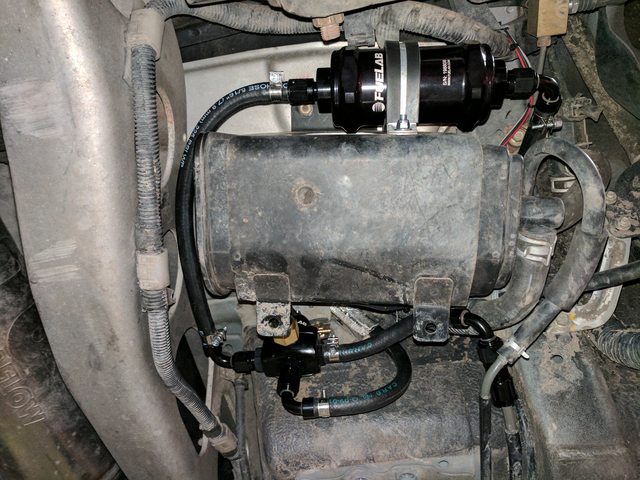
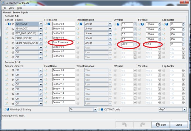
Final FPR/filter config. Filter is a Fuelab 818 with 6ppm fiberglass element (E98/Methanol safe). That feeds into the left side of the Fuelab 535. Return to the tank comes out the bottom, feed to the fuel rail comes out the right and jumps into the OEM line. Not a published use of the 535 but approved by Fuelab nonetheless. Pressure sensor feeds into the MS3 on an analog input. My MS3 didn't have a 5vref on the DB37, so I asked Dimitris to add one - turns out he was one step ahead of me and all current units include it.
Published data on my transducer:
0.5v = 0psia
4.5v = 100psia
Convert to gauge pressure and 0-5v gives you this:
0v = -27.2psig
5v = 97.8psig
Working on IC pipe production samples next, but there won't be many pics of those.
Published data on my transducer:
0.5v = 0psia
4.5v = 100psia
Convert to gauge pressure and 0-5v gives you this:
0v = -27.2psig
5v = 97.8psig
Working on IC pipe production samples next, but there won't be many pics of those.
Reply
1
1
The fixed 0v and 5v really **** me off, cause seems like all the sensors I use are .5 or 4.5 like yours.
Also, I just used Dimitris' wiring instructions to add whatever I want on the DB37. So far 5v ref and tach out. Gotta ditch the little plastic grommet in the DB37 case pretty quickly.
Also, I just used Dimitris' wiring instructions to add whatever I want on the DB37. So far 5v ref and tach out. Gotta ditch the little plastic grommet in the DB37 case pretty quickly.
Reply
-1
-1
Joined: Apr 2014
Posts: 18,643
Total Cats: 1,870
From: Beaverton, USA
It's because the ADC reads 0 at 0v and 1024 (maybe? Not sure how many bits it is) at 5v. So you are calibrating any 0-5v input. Not just sensors.
Reply
1
1
That would be my guess... dynamic vref designs are not particularly efficient when resolution is so cheap these days (assuming proper anti-alias filtering and adequate sample rate). Dynamic control on the low side requires a second ADC or differential front end. At 10 bits, even with the 20% loss in valid codes, you still get resolution that typically exceeds the filtration/sample rate limitations or sensor capabilities.
Reply
0
0
furthermore, with the custom channel feature you can simply bypass the voltage conversion all together and go straight from the adc code to output value. This eliminates some floating point math, which is a good thing.
Edit: even if the use fixed point (unlikely) you teduce clock cycles
Edit: even if the use fixed point (unlikely) you teduce clock cycles
Reply
0
0


