When you click on links to various merchants on this site and make a purchase, this can result in this site earning a commission. Affiliate programs and affiliations include, but are not limited to, the eBay Partner Network.
Investigated the whistling noise and it is a vacuum leak.
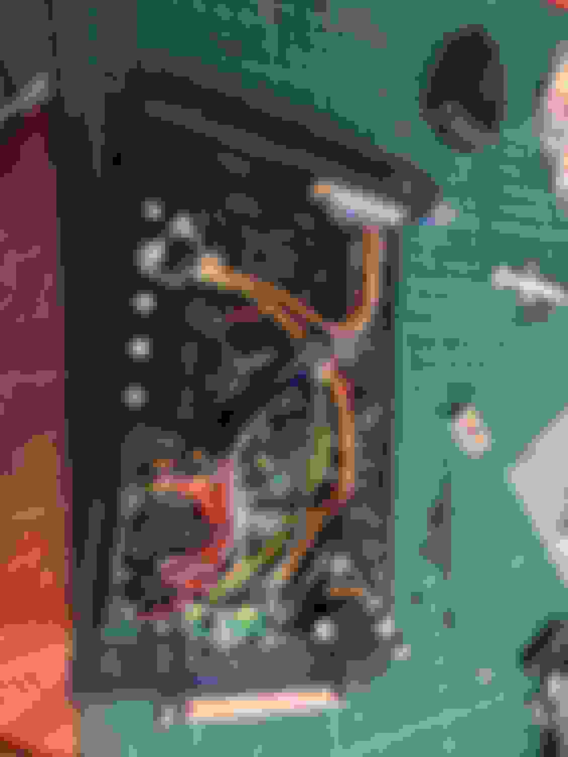
I used my cheapo leak down detector to great effect. I positioned the engine so cyl1 was on the intake stroke, so the air would go through the intake valve into the intake manifold. The throttle and bypass were shut so any air would try to force its way out elsewhere. I used a bit small diameter tube to my ear to listen along the fittings, injectors and WI nozzles and low and behold there was the sound of air around the top of the join between manifold and head at cyl 3 and a tiny bit around cyl4.
Bit of a pain, couldn't stop it just by doing the nuts up tighter so I've taken the sc system off the engine again. Its not too bad of a job while the charge cooler is still empty of coolant. I'll get it all apart and see if it looks like I can flat it out or if I need the machine shop to do a very light skim again. Perhaps welding the WI nozzles so close to the flange has pulled it slightly.
Been trying to fix the vacuum leak on cyl 3 on the intake manifold. Blued it up and it seems welding the nozzle holder on had pulled the upper surface back about 0.1. So I though I would just flat it out on my belt sander, which flatted it out longways but introduced a curve shortways. When then bolted it up to the head the bolt tension pulled the flange about to actually increase the gap between head and manifold between the bolts to about 0.23mm,
So I rang about the 2x machine shops I have used in the past and they couldn't fit me in any time soon.
So I became a human surface grinder instead. I bought a mirror, blued it up and slowly ground high spots (the middle of the flange) down with a 120grit flap disk on an angle grinder. VERY gently and slowly taking a bit off, re-blueing and repeat, regularly checking with a flat edge. It all made sense with the blue though, the blued areas slowly grew and moved into the centre of the flange and the flat edges slowly rocked less and less when checked. When I had it as flat as I could I gently flat sanded it with flat block of aluminium and some 180grit paper, just to take the tiny bit of uneveness in the surface that the grinder leaves. I checked it on my spare head and I have a complete ring of blue around 2 and 3 now, 1 and 4 have a gap of about a thou at the far edges. I took the manifold off the head and checked 1 and 2 with a flat edge and feeler gauge across the bolt holes and I can't get my thinnest feeler through (one thou) with it off the head. I'm not going to chase it anymore, I am pretty confident that with the new gasket this one thou will be taken up. I think at this stage I'm more likely to butcher it than help it. The rock is completely removed, and I will check with my leak down tester when I am reinstalling. I found this method here and so far it seems to have worked well
I have added the Tiny iox and the WI circuitry to my MS2. I added a new DB15 connector to the front just under the LEDs. It just fits there with the connector and a tuning cable / bluetooth adapter in the DB9 connector.
I used hot glue under the Tiny iox to make sure any risk of components shorting to the main board was removed, and then hot glued it in place. It just clears the case. Hot glue might (and probably is) a bit of a bodge but I find it works really well. It is strong and stays in place but can easily be removed with a hairdryer if required. I use it on the jumper wires too to prevent them vibrating and breaking, another tip I've picked up recently.
I added the WI flow sensor to the back of the dist manifold, then I pulled through all the new wiring from the engine bay into the cabin ready for wiring. Going to try and complete all the wiring tomorrow, then I should be able to start engine not running testing of the WI system, just checking it does what it is meant to while still stationary with the nozzles in a bucket.
Flow sensor just on the back of the WI dist manifold
Not too many photogenic pieces of progress, but progress non the less.
I reinstalled the supercharger system and fired it all up, it doesn't appear to have any vacuum leaks anymore which is a result. I let it idle up to temp checking for leaks with a hose and I couldn't hear anything, I pulled the plugs after to check the colour and they were all the same so I think we are ok now. Also this was the first time firing it up after converting to sequential ignition, so that seems to work too.
I have made good progress on the electronics for all the new sensors and WI, although it always seems to take three times as long as you think it will. Still got a couple of bits to wire up in the footwell, the WI status LEDs and the pump / tank level sensors, although all the cabling is run to the boot now. It is a complete PITA trying to untangle and make sense of so much wiring in the footwell, but I made the WI loom in basically two parts that just need joining together in key places which has simplified things a lot. One key think I found is that the ends of thermocouple cannot be soldered! This is the thermocouple for the supercharger outlet temp, that needs to be joined to the DB15 plug on my ECU. I'm going to have to use a screw terminal adapter before the DB15, and hopefully the temperatures of the joint will be the same as inside the ECU so it doesn't muck about too much with the joint temperature compensation and throw my readings off.
I also made contact with the TinyIox through my MS2 to set it up. I updated the firmware, added it to my project and setup all the table offsets. The temperature sensor circuits all react to being grounded etc and I can see the data through the gpio channels on my MS2, so it seems to be working as expected. I had a bit of fun setting up the inc file for the thermistors but that seems to be resolved, atleast it doesn't throw any coding errors, still yet to see if they produce sensible temperature readings. I also haven't tested any outputs yet but I should be in a position to do that this weekend, to try to spray some water through the nozzles with them mounted into a bucket and see everything works as expected.
I got it out in the sun this afternoon and seeing the manifold out in the open in decent light for the first time was a treat. The colour is coming up a treat, it makes it all worth it. :-)
Yeeeeeahhhh
The sound level with the new exhaust is definitely not an issue, I don't actually think its any louder than the last one now. Certainly not going to be an issue on track.
I got all the wiring in the footwell completed, everything works and is feeding into the ECU / tunerstudio. Nothing self immolated which is a bonus. EGT all works, charge cooler temp sensors all giving sensible readings, the post sc temps sensor was working although I didn't really process what it was saying particularly.
The only odd thing I noticed was that my WI flow sensor was reading about 13ccmin when I know nothing was spraying - I need to see what it does when I am spraying something. The wiring was a bit of a guess on this sensor, there isn't much info out there on how to use it as a standalone unit. It is a hall sensor, producing a 5v square wave. I know it needs 5v supply, and a ground.
It has 4 wires, 2 of which had continuity at around 0 ohms, so I took those as the ground and cable shielding. I took a punt on one of the wires being the 5v supply and the remaining the signal. The Tiny provides a 5v pullup to the signal wire, and my expectation is the sensor grounds and pulls the Tiny PWM in pin low when it is working, just like a crank sensor.
This is the circuit I am currently using. I kind of think there should be a capacitor or diode to ground in the ECU for protection. Anyone out there give me a bit of critique on it? Any help would be appreciated. Also slightly annoyingly the whistle is back - but intermittently. I gave it a bit of a rev up when it was warmed up, and it started I think when it saw full vacuum, rather than just idle vacuum. I don't think it will be a problem for the MOT because it idles fine at good AFRs, so I will investigate further after that. I think the flange is not quite flat enough somewhere, I'm going to line up the machine shop for sometime before the trackday, but I can carry on getting the car up and running in the meantime.
So this is the high speed input on an MS3, used for gear tooth sensors, abs rings etc. High frequency signals like my flow sensor will (hopefully) produce.
PT4 goes to the DB37 connector and then out to the sensor. IGN2 is the processor pin (that seems to be what it is saying).
Not a million miles away from my circuit. The MS3 circuit appears to lack the +5v pullup my circuit has, but It does have what I believe to be overvoltage protection in the form of the 2x Schottky diodes to vcc and ground.
I don't think my 5v pullup will cause any harm, even if it turns out the sensor does have an internal 5v pullup. Both pullups would be 5v, and they would be in parallel, so I wouldn't be accidentally generating a 10v signal or anything like that.
I will run a log when I start testing the flow sensor and just see what it does. I'll work out / confirm the external wiring is correct then add the protection in the ECU once I've got it reading correctly.
Making steady progress on commissioning the WI electronics today. It is a bit two steps forward one step back but it will get there.
I didn't take any photos so apologies its a bit wordy, I'll get some tomorrow.
I made a little bracket for four LEDs, that will give me the status of the WI system. I mounted this on the top cover of the steering column, in front of the instrument cluster. The four LEDs are for WI system on / ready, tank level ok, WI system active - flow ok and map changed and tank getting low (non critical). They are right in your view but don't block the view of anything important. I'll get a pic tomorrow.
I flipped the main WI on switch for the first time and the first LED came on, then I went into the boot and jumped two wires to simulate the lower tank level sensor being on. This activated the main WI relay and the second tank ok LED as it is meant to. Had a bit of an odd issue when I tried to jump the wire that is for the tank getting low sensor, it shut the whole system off and deactivated the relay. Bit of a head scratcher really as I thought this bit would be the simplest circuit / LED to sort. I think it might be backfeeding the other LEDs and the main relay somehow. Need to try some ideas out to solve, but it's not a critical part of the circuitry, it doesn't actively do anything other than light up an LED to tell you the tank is getting a bit low.
I activated the pump relay no issue, worked without a hitch from the Tiny.
I tried out my map switch circuit / LED and it wouldn't light the LED. I checked the ECU side and that was fine, the transistor was working, providing continuity to ground but for some reason the lead from the LED to the ECU was not at 12v when it should be. I've traced this to some inline resistors I added to dim the LED, I either went a little overboard or there was a connection issue, so I think I found the problem, just need to rewire it up properly.
The solenoid valve didn't sound like it was working, when I tested it, although it was warmish to the touch suggesting something was happening. I checked it and it had 12v feed bur a lot of resistance (1k ohms) to ground when the ECU had activated the transistor, and it should have really been 0 or atleast very low resistance. I traced it to the ECU itself. I removed the ECU and checked my wiring again and there was nothing to suggest why there was so much resistance. I have swapped out the transistor to a trusty TIP122 and I am driving it past saturation so it should open fully (possibly the issue on the last transistor?). I have also removed the zener diode that I was using as a voltage clamp get the solenoid to close quickly. I am going to put it back in the car with the case open tomorrow and see if the resistance has dropped with the new transistor, then add the zener back in (I don't think this is the issue but I just want to work through it systematically).
I'm also going to take various voltage measures on my map switch circuit just to make sure the map switch pin sees a low signal when it should do. It goes through a couple of transistors to get to ground, one which is activated when WI is ready and the tank level is ok (2x LEDs on) and then another which is activated by an output on the Tiny which switches when the flow readings are acceptable. I'm just using other parameters like TPS at the moment to fool the system and get voltage and resistance readings.
I swapped out the PWM valve transistor for a TIP122. Same issue, high resistance to ground when it should be virtually 0. I measured the voltage on the base pin and my multi meter said 9v. It doesn't make any sense to me as the tiny doesn't even have a 12v feed, its all 5v. I've disassembled the tiny from my input / output circuits and will rebuild on a bigger PCB to give more space between components.
Before I do that though I will check the voltages straight off the Tiny output pins for each one of my outputs just to check they all give the expected 5v when requested. Previously my various jumper wires made them inaccessible. Hopefully I have't fried anything. I will also fire the valve manually by grounding it outside the ECU just to step through everything.
Just a bit frustrating really because there isn't anything to my mind that makes the PWM valve circuit difficult. There is a 12V feed to the solenoid, the transistor grounds the other end of the circuit to drive it. Nothing complex there, yet it seems to be giving me a really hard time. The resistance is definitely across the transistor, the circuits either side have continuity at low resistance to there respective ground / component as the should.
On the upside I think I have realised why my flow valve was giving me a reading of about 13ccmin - it is calculated from the number of CPU clock counts between signals within a certain time frame as far as I understand it, which gives the time interval between pulses that the frequency can be calculated from. I have some info that gives a translation between frequency and flow rate. With no flow the number of CPU counts is the number of counts in the defined time frame, rather than the counts between signals. This is a value and it happens to equate to about 13ccmin, which is effectively my minimum measurable flow rate. Hopefully that's it anyway.
I've got 2 1/2 weeks before my trackday to MOT, remove charger, reskim manifold, reassemble and figure out and base tune the WI - loads of time
So I had another quick play today to check some of the WI electronics.
I separated the tank low LED from the same ground wire as the WI on and tank critical low. This stopped the weird behaviour I saw previously. Must of been backfeeding the circuit somehow, though I still haven't worked it out in my head yet.
All the output pins on the Tiny iox output 5v when requested, so I haven't fried anything which is excellent.
I can fire the PWM valve manually by grounding it. So there is nothing wrong with the car wiring, the issue, as suspected is with the transistors.
I was doing more research last night and think I have sort of got to the bottom of the transistor issue. I think a combination of incorrect sizing and incorrect base current being applied for the load, which then gives an overly high level of resistance across the transistor. Still not exactly sure but I will get there with some more research.
I'm going to use a VNP35N07-E MOSFET now. It is far in excess the required current handling capability at the gate voltage I will apply (4.5-5v) for my application and it has the bonus of having a built in voltage clamp. I understand this MOSFET was designed for high z fuel injectors, which from a load point of view my solenoid is very similar. Hopefully I will have more luck 3rd time round.
I've also started rebuilding my Tiny input / output circuits on a new larger board, with a couple of changes. I am going to feed my sc air temp thermocouple into an external amplifier, like my EGT sensors. I noticed the temp readings were higher than they should be with engine cold and off. I think it is to do with me extending the wires (which I thought might be an issue). This means the circuit inside the ECU is just a normal ADC input now. I have also added a resistor into my flow sensor circuit - I noticed this was another difference between my circuit and the MS3 high speed input. I think its there more for protection from shorts or spikes more than actually being required to measure a signal. I have also built in some refinements to my map switching circuit, adding a seperate transistor for the WI active LED rather than trying to bring that 12V circuit into the map switch 5v circuit and protecting the tiny from being back fed by using diodes. Separating them makes more sense with a bit more space. Also the components are just laid out better and more clearly with more access. If I need to swap out a resistor now I have room to get in there without taking the whole board apart or burning everything with the soldering iron.
I promised a pic of the interior setup so here it is. 4x LEDs in front of the instrument cluster, main switch is the top toggle switch on the tombstone between the gauges. On my little boost / afr gauge pod down where your right knee would be is a little headphone jack. That is wired to the knock sensor before the filter box, so you can plug in a headphone amplifier and headphones and listen for knock. Hopefully will work well for tuning and it will be really easy to access.
MOT tomorrow, everything seems fine with the car, had a good check over. I'll take my laptop anyway incase the fuelling needs a tweek. Then I have hopefully lined up the machine shop for friday afternoon to do a skim of the manifold to hopefully rid the whistle once and for all.
Car passed the MOT no problem, not entirely surprising bearing in mind I've pretty much rebuilt the whole car in the last year but relieving non the less.
Was great to have it out on the road even on the very short trip to the MOT garage. I forgot what it was like to drive and the exhaust sounds great, even if I only took it up to about 4k.
I didn't hear the whistle but equally I haven't done anything more to address it. I haven't heard back from the machine shop and I'm not going to strip it all off until I know for sure they can fit me in.
I'm going to try and take it on a couple of decent trips in the next few days just to check it all over, get some logs etc. I may postpone the machine shop work to avoid missing the events at the beginning of April.
The engine mount I made certainly has had a large impact on NVH. Its not unbearable but the interior all vibrates at idle. Hopefully it will soften up a bit, but I will probably swap in a softer bushing next time I have access to it.
Other good news is that I finally have the WI functions working on the car.
I redid my output circuits from the Tiny and used a different transistor (actually a MOSFET this time). I just tested it first with engine off, using tps to trigger the PWM valve and it worked with the WI main switch on, and didn't with the switch off, like it should. It is quite loud though so I will look at isolation options in time. I've also got the map change LED working and also got the ECU to switch maps with the engine running but only with WI switched on as designed.
Next steps is to get the tank and pump mounted and piped, and fit the nozzles and point them in a bucket to bench test the system and hopefully see the flow sensor working.
I ended up oversealing the inside of the tank along the welds. Because I didn't backpurge it there was a lot of loose sugaring coming off them. I cleaned it out many times but couldn't get it clean, so I got some marine sealant, designed to be submersed in water and applied it along the welds to seal them off and stop any more material flaking off them. I doubt the stuff is properly methanol compatible, but I'm not going to worry about that and just run 100% water for now. The greater danger was the weld flakes that could easily clog one or more of the nozzles despite the filter and it just seemed stupid to chance it. I'll revisit the tank - if I stay on water only I will make an ali tank and save some weight, if I do go down a more methanol based mix I will look at other options, either an off the shelf tank or remake my tank but backpurge it. Live and learn but I think I have addressed the issue short term to be able to get some testing and data aquisition done safely.
So I was playing around in Tunerstudio yesterday and a potential issue arose with my flow sensor setup.
I need to use the raw PWM input value, as this is a channel that the processor actually sees while driving, which as I covered before is the number of CPU clock counts between a maximum interval of time, which is set by the prescale for the input. The clock speed is very high, default is 24MHz. This means that you are dealing with values far higher, in the tens of thousands, to use as conditions to activate or deactivate outputs (for map switch) than say MAP, TPS or even rpm would use. Maximum raw PWM value is 65536 (turns out to be largest 16bit number), this represents a flow / Hz of below the minimum measurement possible (interval between input pulses greater or equal to maximum interval for given prescale).
The maximum value Tunerstudio for an output condition is 32767. This is the largest 16bit number with a decimal possible. The potential issue I twigged with this is that I can basically only use half of the potential range of raw PWM values to trigger any outputs. The range of values greater than 32767 up to 65536 are not valid for the output conditions. This range represents the lower frequencies / flow rates that could be measured.
What also needs to be considered it that the relationship between the raw PWM count and the Hz / flow rate is not a linear one, it is exponential. See graph below. Basically there is an area in the high frequencies / low raw PWM count that has a very low resolution. A small change in PWM count results in a huge change in frequency (flow rate) and so is not ideal to use for accurate and consistent readings. Basically there is an area in the middle PWM raw count that I can use as an output condition and has good stable resolution. What I needed to do was make sure that these values correlate to the range of frequencies I expect to see from my flow sensor including the minimum flow to trigger map switching, and a little bit more to cover a burst pipe event.
The way to scale the raw PWM values against a frequency range is by using different clock speeds and prescales. I'm going to be honest I haven't got my head entirely around the exact mathematics calculating the max interval from the prescale, but luckily on JBperf.com Jean put together a neat little clock speed & prescale calculator on the info for the i/o extender board. This gives you the max interval for a given clock speed and prescale, which is the headstart I needed to be able to work out the rest of the maths.
The relationship between raw PWM count and time interval is a linear one. When raw PWM count is 0, time interval is 0 (infinite frequency) for any clock speed / prescale. Using the info from Jean's calculator for maximum interval, achieved at a raw PWM count of 65536 you can calculate all the time intervals for the raw PWM values in between 0 and 65536, and from the time intervals you can calculate the associated frequency for each raw PWM count for a given clock speed and prescale.
Interestingly I twigged that the maximum frequency for a given clock speed and prescale given on Jean's calculator is the Hz value of the raw PWM value of (65536 / 256) - 256 being significant because it is the largest 8 bit number with a decimal.
Anyway, with my nozzle sizes I am really interested in the 100 to 450ccmin range, representing 22% --> 100% flow of my nozzles, which equates to the frequency range of 16Hz to 75Hz. So this range of frequencies need to land in my green zone on my graph, with a bit either side.
In the end I settled on using the default clock speed of 24MHz and a prescale of 64 for this application. These are the values you see in my graph above. This allows me to switch maps from flows of about 70ccmin, and measure flows with good resolution up to around 550 / 600 ccmin, before the relationship starts to get silly.
Good learning experience, I haven't had any experience of clock speeds etc before, but yet another reason I should have just bought the complete Aquamist kit and have done with it
Wahhhhhoooooooo has that exhaust made a difference. I ran a log of my complete test drive (luckily, but we'll get to that) and I did a couple of good pulls. See the dyno runs from virtual dyno below. First pull (blue line) is on as flat of a road as I can think of and the second pull (red) goes up a mild hill (not steep or anything, but definitely and unmistakably uphill). Green is the old 255whp run on the old exhaust. Take them with a pinch of salt, the hump in power from 6krpm to 7krpm on the blue line I think is some wheel slip, and I think the red line 6krpm is effected by the hill because it goes a bit flat and odd (still 270whp though :-) ) My take is that the actual value is somewhere between the two, so more testing required, but looks hopeful. The other thing of note, which is there is no question off hills and wheelslip is that I am now about 0.5AFR leaner at WOT than I was before (11.5 vs now 12.0). So I think we are realistically looking at something between the two runs at 270 to 285whp now. I did also turn the rev limit up to 7400rpm - looking at this though it suggests that might not actually have much point. I'll get some more data and go from there. Looking very positive though, this seems to have made up the 'lost' horsepower I expected from the pulleys back last summer.
Yeah yeah yeah yeah yeah
On to the bad, because it always has to kick me in the knackers.
The whistle is back, needs sorting really although it doesn't seem to affect drivability at all.
On the last pull I did I encountered a problem. It made full 1bar of manifold pressure, then lost power. I saw on my boost gauge it was only at about 6psi, so I got out of it. On the log it confirmed the above, but with the added detail that the car went lean at the same time the boost dropped off. I thought maybe the bypass had failed to shut fully or something like that, but that wouldn't explain the lean condition. Pulse width on the injectors was normal and also it didn't feel lean, with any of that stuttering and hesitation. It just felt a bit flat which is why I looked down at the boost gauge. Off the boost on vacuum in cruise everything was normal, at normal AFRs, and it idled fine etc. I've had a quick look and I can't see a popped off hose or anything so far. More investigation needed but I think there is no doubt I need to sort the manifold flange out. I'll take a more detailed look in the logs and see if the sensors show any more clues.
Are you running a 11:1 AFR because you make more power or it's safe?
When I was supercharged only, I found that I made more power in around 12:1.
Safety. Didn�t know how good the manifold distribution was and the warm AITs meant we wanted a bit of a cushion in there.
Also at the time of tuning last year we hadn�t twigged the offset between gauge and ecu afr reading, and I haven�t fixed that yet, so reality is the tune was slightly richer than it should be.
Gauge reads about 11.7 afr at WOT now, instead of 11.2, with no change to ve table just the exhaust and the bit of detail work I did on the manifold.
I didn�t have huge luck logging the extra sensors, some weird values coming through, which is odd because they view fine in tunerstudio when driving, but the raw adc for the 4x EGT sensors were within a 40degC range of each other, cyl 3 being the hottest.
*Just a disclaimer :-) because I was all very excited about the 'dyno' results last night, the only ray of sunshine from the drive.
Not a chance it is making 300whp, but all signs point towards some level of performance improvement over the previous results.
The two latest pulls on the dyno sheet don't look quite right to me with more inspection.
The blue trace has the big power hump between 6k and 7k and I just don't see being realistic, as I've said previously I think being effected by wheel slip.
The red trace shows peak hp being made at 6144rpm, the old green trace was making peak hp right at the end of the run, in this case 6868rpm - a good 700rpm higher. I have also already lifted off before the end of the red trace, you can see the boost drop off in the lower graph. I checked this in the log and it was because tps% had dropped, rather than the first occurrence of the massive boost leak I had on the next pull. It was also on a section of road that goes from flat to uphill out of a roundabout, which is going to effect the figures slightly.
There is some interesting info in there though, if you look at the torque before everything goes a bit haywire at 6krpm+ you can see the blue, red and green tq pretty much together through the 4500 - 5500 rpm range, blue slightly above the rest at 4500rpm but then coming down to meet the other traces. At 5500rpm the old green trace rolls over and starts to reduce, whereas red and blue continue to climb. Red rolls over next at 5775rpm and 235ftlb, blue still going. At 6krpm both red and blue are making around 25ftlbs more than the old exhaust trace. This was really the point of the exhaust, trying to extend the torque curve higher into the rpm range rather than clipping it early with a flow limitation.
Hopefully over the coming days and weeks I can get some better logs and more reliable information. I might try and use the gps receiver and see what Tunerstudio reckons, the gps should eliminate any wheel slip issues showing up as increased hp, actually it would show a reduction in hp from lost forward motion.
Supercharger is off the car now. No obvious signs of anything popping off. Bypass works fine, injector seals all look good. Supercharger is fine, rotors all untouched and no marks in the case. No popped off pipes or sensors.
The whistle can't be ignored as a factor. It shows that for sure the manifold is not properly sealed to the head. The flange width has also got quite thin in the middle from both the original machine shop flattening and then my totally professional sanding job, down to about 4.5mm from the original 8mm in places. I saw that before I did my mirror / flatting job by tightening the bolts on the head that the flange could be deflected a measurable amount. I do wonder if what I am now seeing is a deflection due to the vibration of the engine, making it whistle and then under full load the extra force pulling the supercharger downwards from the belt drive opening up the flange to head joint slightly and dumping the boost. Being so close to the injectors I can see this also dumping fuel too - which would explain the lean condition. Its really the only hypothesis that makes sense with what I saw in my logs, and to be honest when I was reinstalling the thickness of the flange in the middle did have my engineers spidey sense going.
All is not lost though, I can reinforce the flange fairly easily and hopefully get it into a machine shop to flat it all back up post reinforcement. It ran fine and supported the sc fine last year, there is no reason I can't regain the strength back with a bit of work and get it running properly again.
I also had to drill out the bottom hole on my reinforcement arm 1mm to get it to fit, as my sanding had changed the sc position very slightly. I wonder if this tiny extra bit of clearance is allowing the sc to pull down more than it used to. I will take a look at this also when I have the manifold refaced, maybe weld the hole back up and redrill to remove any potential slop.


 0
0