When you click on links to various merchants on this site and make a purchase, this can result in this site earning a commission. Affiliate programs and affiliations include, but are not limited to, the eBay Partner Network.
We plugged the dyno in to my tach output this time so it could do the torque calcs.
The figures it gave were based on engine hp. My previous calcs were based on whp.
I have roughly translated the torque back from whp and it seems to correlate to around 220lbft, which is where we were last year, and around what I was expecting from the sim.
So we seem to be fairly on the money with the sim which is good.
To make way for the big filter and airbox, part of the requirement is to move the wiper motor out of that area.
I had been scratching my head about it for a while, how to move the motor into the cowl area.
In the end I had a bit of a brainwave and mounted the motor inside the cabin, with the spindle coming up vertically through the floor of the cowl. The stock bung works nicely to keep the any water out and I put sealant under the bolts. I then just shortened the wiper link to the new dimension. Still need to do a final wiring neaten up, but I am very happy with the solution.
Don't ask why I've removed the cabin blower intake mesh, no idea. I'll get some mesh and redo it. Motor tucked under the dash. Fits like a dream. The catch can will be moving, and it all starts to look quite reasonable fitting the big filter and airbox in this corner.
I started a bit of work on making the mould for the new airbox. It's just a block of polystyrene foam, measured out and carved into shape. There will be another part to the mould that I need to make which is the intake section that will require the removal of the cowl wall in that area. I wanted to make sure the main box body worked with the dimensions I wanted, internal clearance to the filter etc before I got trigger happy with the angle grinder on the car. The intake area should be more than enough, about 21,250mm2. This is compared to the old intake area of 4185mm2 of a 73mm ID pipe that lead into the airbox previously. Hopefully this area coupled with enough clearance to the filter all around it will keep the filter well and evenly fed, best replicating the dyno test setup but with an airbox, cold air feed and actually fitting in the engine bay.
You can see the centre point for the outlet of the filter marked on the box. There is a reasonable amount of clearance to the exhaust, but I will improve the insulation over my current silver tape as it will be closer than it was.
The idea is to then layup the carbon over the polystyrene, with a peel ply between them. Polystyrene apparently doesn't react with epoxy resin, although I will do a sample test first. I will do 3 layers of carbon, then peel ply, then breather fabric and vacuum bag it. Once it is set I will melt / hack the polystyrene out the middle of it to leave the final component. Hopefully with careful smoothing of the polystyrene and vacuum bagging it will look professional. It should produce a matt finish on the outside which I think should look cool but not flashy. I can clear coat if it looks a bit rubbish.
I've chosen this method because I'm only looking to make one of these, and making a two or three piece outside removable mould seemed a bit overkill. I could always take a mould from my part if someone did want one if it comes out alright.
Current thinking on the catch can is to relocate it under the wing / fender behind the front wheel outside the engine bay, and run the breather hose through the structure with a bulkhead fitting. I think the engine bay will look a bit cluttered if it is in front of the new air box. Just my current preference.
Anyway this will be my last update before xmas, so have a great holiday everyone
I have got the whole pattern for the part shaped out of the polystyrene foam.
It's alright to work with. It's really easy to quickly get to the rough shape, but difficult to get fine detail. I used a saw and hot wire to get down to a very rough shape then 120grit sand paper to get to the final size / shape.
120grit seemed a good compromise between material removal and tearing it to pieces. Because the material is basically made up of tiny little ***** it is really easy to tear holes in it, and this is also why its hard to get the finer details, in areas like the intake through the cowl.
I think I might use some waxy material to fill in any imperfections, before wrapping it in film before I start laminating the carbon fibre over the top of it.
Nice job, would not have the patience to make polystyrene foam look that nice. For your next one, blue foam board is heaps easier to sand to shape
Thanks Harry, it is still a bit rough (flaky) around the inlet but I'm hopeful some rework will output a good mould shape. It works really quickly, you have to be careful to be gentle with it.
Initially I was put off the blue foam board because I couldn't get it in big blocks like the expanded polystyrene I have to do the whole box in one piece. I thought gluing multiple thinner sheets or blocks together would be a pain (movement between them, falling apart etc)
The reality is I have now made this mould out of 3 parts anyway. It was dead easy with a hot glue gun to get a good joint between the parts.
The bigger issue is getting a decent surface finish which I'm sure the denser blue foam would have been better for. Lesson learned for next time I think, and would save you some trouble Pat.
Last time I was working with foam board, the blue surfboard foam was MUCH more expensive, but better in every way. Prices may be different now though, that was a few years ago.
Last time I was working with foam board, the blue surfboard foam was MUCH more expensive, but better in every way. Prices may be different now though, that was a few years ago.
The 30x30x30cm block I bought was �14. Compared to the denser purpose made moulding foams it was about a 1/3 of the price.
I have smoothed out the intake area using a water based filling compound - cough wall filler cough
It seems to have worked well, bonded and was easy to sand back. I didn't want to use any auto body filler because I had heard the chemicals in that would eat the polystyrene.
The wall filler will just crumble out with the peel ply, I am not worried about getting it out of the part after it is cured.
First, I needed to make a stand to hold the mould that allowed me to lay the carbon over all the required surfaces, so some scrap metal and a couple of bits of studding did nicely. They poke into the mould at the inlet mouth. Also I had to make the adapter / shut off valve to go between my vacuum bag fitting and the hoover. I had the valve lying around as well as some convenient adapters / silicone hose. Did the job nicely.
Then on to the main event. First I applied the peel ply fabric to the mould, you can see it in the pic above. It has stripes on it to make sure you don't forget its on the part. It was not very easy to get it to conform to the mould so I was dreading what the carbon would be like. I didn't take many photos because I was working quickly and had a lot to do before the resin started curing.
First layer went on ok. I laid the main top, front and bottom faces in 2 parts, with the split on the bottom. I then slit the sides of the carbon to allow it to conform around the side faces. Then smaller sections for the side faces over the parts folded in. Second and third layers were then a repeat, but moving were the joints / slits were to make sure I didn't have them in the same place as the last layer. These later layers went on a lot better as they properly stuck to the previous layer, and would form nicely and more easily because of this.
I made sure that the faces that will be most visible, the top and front had the best, uninterrupted weave. The outer side that will be against the wing that won't be visible when installed has all the weaves coming together at different angles because of the way the fabric drapes. The inner side will mostly be hidden by the mount system for the filter, but I tried to give the bit on the inlet that will be visible a complete weave pattern.
After I finished laminating it all I wrapped it in another layer of peel ply, then the vacuum bagging cloth. I then put this on a layer of vacuum bag film, applied tape around it all, before putting the top vacuum bag film on the tape to form the envelope, ensuring the vacuum bag fitting was in there. Making the vacuum bag is a PITA, the tape is so sticky and your dealing with large bits of film, really easy to get it stuck in the wrong place and have to start again (It took me 3 tries). Then plugged in the hoover to pull the vacuum. It worked great but I did have to do some leak hunting to be able to just shut off the valve and stop the hoover and the bag still hold vacuum, but we got there.
So now just need to wait 30hrs for it to cure fully and see what it looks like. Fingers crossed.
Part had cured this morning, so I started unwrapping it.
Being totally honest I'm a little bit disappointed. After the wet lay up yesterday and how good it looked shiny with the wet resin I was going to pack in my day job and start making Formula 1 cars
The reality this morning is now in a matt finish it looks a bit rubbish (easily fixed I think, and expected) but there are a few places I think the vacuum bag / outer peel ply has caused wrinkles in the part.
Mercifully these are concentrated at the outer side of the part (not visible with the part fitted). So I would give the part 70% when viewed from angles it will be seen in the car, 50% overall. I will have to melt the mould out to see what it looks like on the inside.
These folds I think are a reality of this method because I was basically relying on the peel ply and vacuum bag for the final surface finish, because the mould is on the inside of the part. The vacuum bag particularly wrinkles as it does it's job, that is just a reality, so in areas of high wrinklage (complex forms and hollows) the part has suffered in places. If I had used my foam pattern to make an outer mould with a nice smooth outer surface, that I could then use a release agent on rather than peel ply the results would be a lot better I think. However this shape would need at least a 3 piece mould, and this is my first CF part ever. I didn't want to bite off more than I could chew. As it is I am sure the part will be absolutely fit for purpose, but perhaps not as beautiful as it could be.
This is the visible view in the car, not too bad, there is a fold on the intake area corner, and a small fold on this front corner. Outer side is a little bit more of a car crash to be honest, but it won't be visible
I'm in two minds what to do. I could sand down the little bits of the part that have wrinkled that will be visible then do a final aesthetic layer of carbon over it. With the part being dry now I could do a better job cutting very precise shapes for this lay up to give a very neat finish, but I run the risk around the corners of getting air inclusions because I won't rebag it - that could end up looking far worse.
Or I could just do another coat of resin or clear coat it to make it shiny (which I think as a whole would make it look tons better) and just accept there are a couple of little faults in it. Not sure which route to take at the moment.
I got the foam out the middle of the part, just used a heat gun to shrink the polystyrene down and break it up then pulled it out with the peel ply. Was a bit of a struggle but not too bad.
I was very pleasantly surprised by the inside of the part. All the radii inside are nice and smooth, so it should work as well as intended. Bit of gluey stuff to clean / sand off but the actual carbon is a nice smooth radii
I wet the outside of the box to see what it would look like with a bit of gloss, I like it a lot better.
You can sand down, coat liberally with resin, then block and wet sand up to 2-3000 grit followed by polishing. You will be surprised on how well it will end up looking.
You can sand down, coat liberally with resin, then block and wet sand up to 2-3000 grit followed by polishing. You will be surprised on how well it will end up looking.
Thanks Harry, will do. I have already had a go at it a bit in places to as a few of the imperfections seemed to be mostly resin anyway and it has certainly helped, still a little lumpy in parts but better than it was.
I'll give it a good resin tomorrow then give it a flatting and polish.
I cut some steel off the miata yesterday because I now plan to make a new trunk lid from carbon after seeing your progress!
Looking badass sir! FWIW when I was on the racing team at university we commonly made parts where one side had to be perfect, the other didn't.
So intake manifolds, inside was perferct but defects on outside ok.
Body panels the opposite. So I think you're fine.
Ha ha cheers Pat, comforting words! Yes tell me about it, carbon trunk.... carbon bumpers..... carbon hardtop..... carbon doors and quarters... oh dear its escalating!
The biggest pain is the space required to make the parts. The airbox isn't even that big but bagging it up took the whole dining room table.
I gave the part a very liberal coating of resin after sanding down a lot of the problem areas. Looks loads better. It's been drying overnight but I will give it another 12-24hrs before I flat it, but I am pretty hopeful it is going to come out fine
I realised I needed to bite the bullet and cut the cowl to test fit the box sooner rather than later, to check it would fit and also to be able to start having a look at intake routing and catch can requirements, as there will be a few parts to order for these.
So out came the angle grinder and I'm pleased to say it fits like a dream I cut the cowl about 1cm larger than the intake neck, as I am going to use rubber seal on the edge and this needs a bit of space.
There is a few mm wiggle room for me to be able to mount it without it being hard up against the metal of the car. I will use some sticky back foam in the couple of points it is very close just to stop any rattles.
I'm going to make a new slim line catch can to fit between the airbox and the brake pipe / loom on the bulkhead, tucked behind where the intake pipe will be. Seems the most sensible place to put it and gives me some welding practice. Seems more sensible than running the breather through the car structure into the gap under the front wing like I had thought of doing previously.
Before I do the final flat and polish I need to test fit the parts that secure the filter in place, and check the filter sits where I designed it in box.
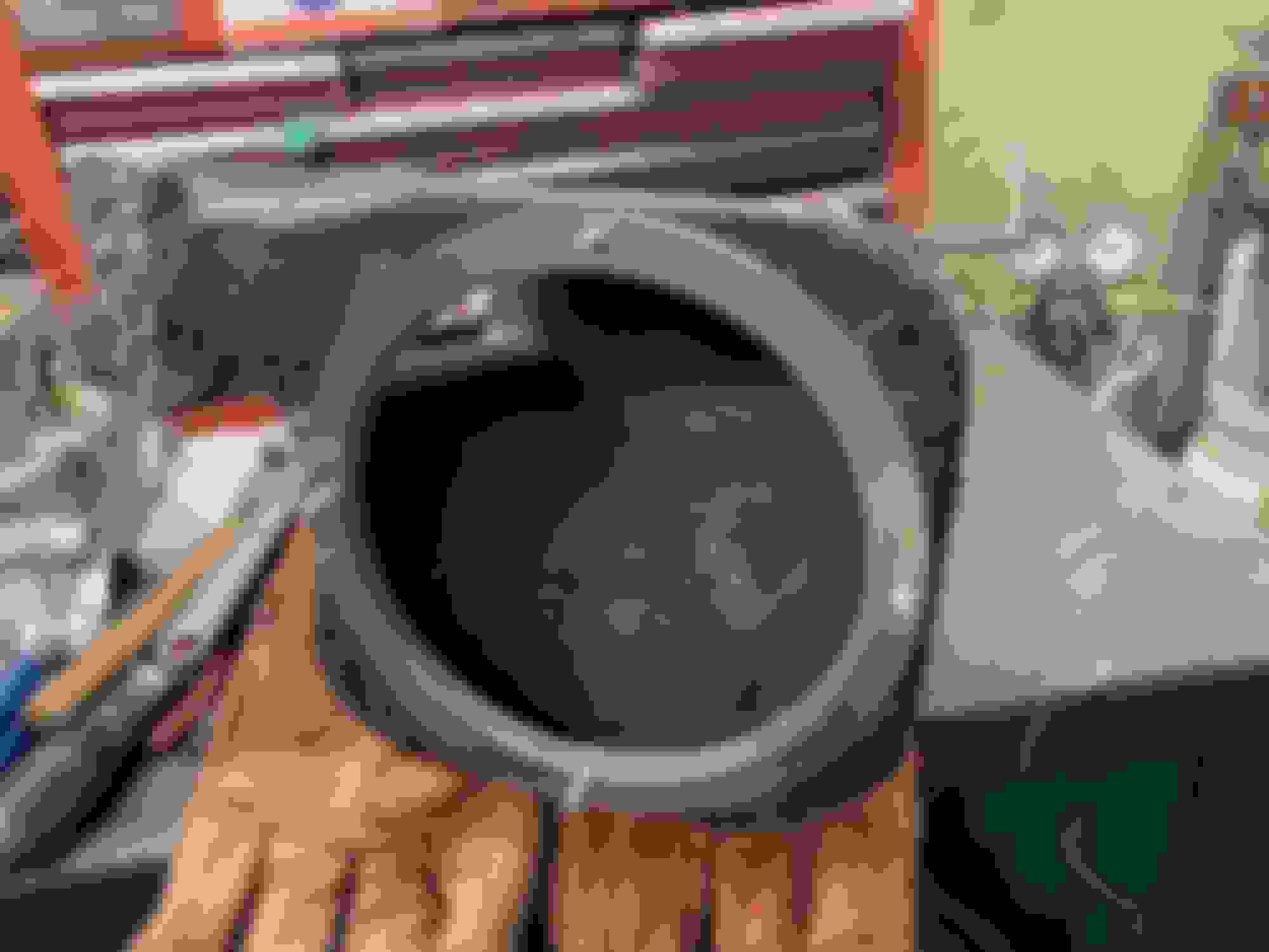
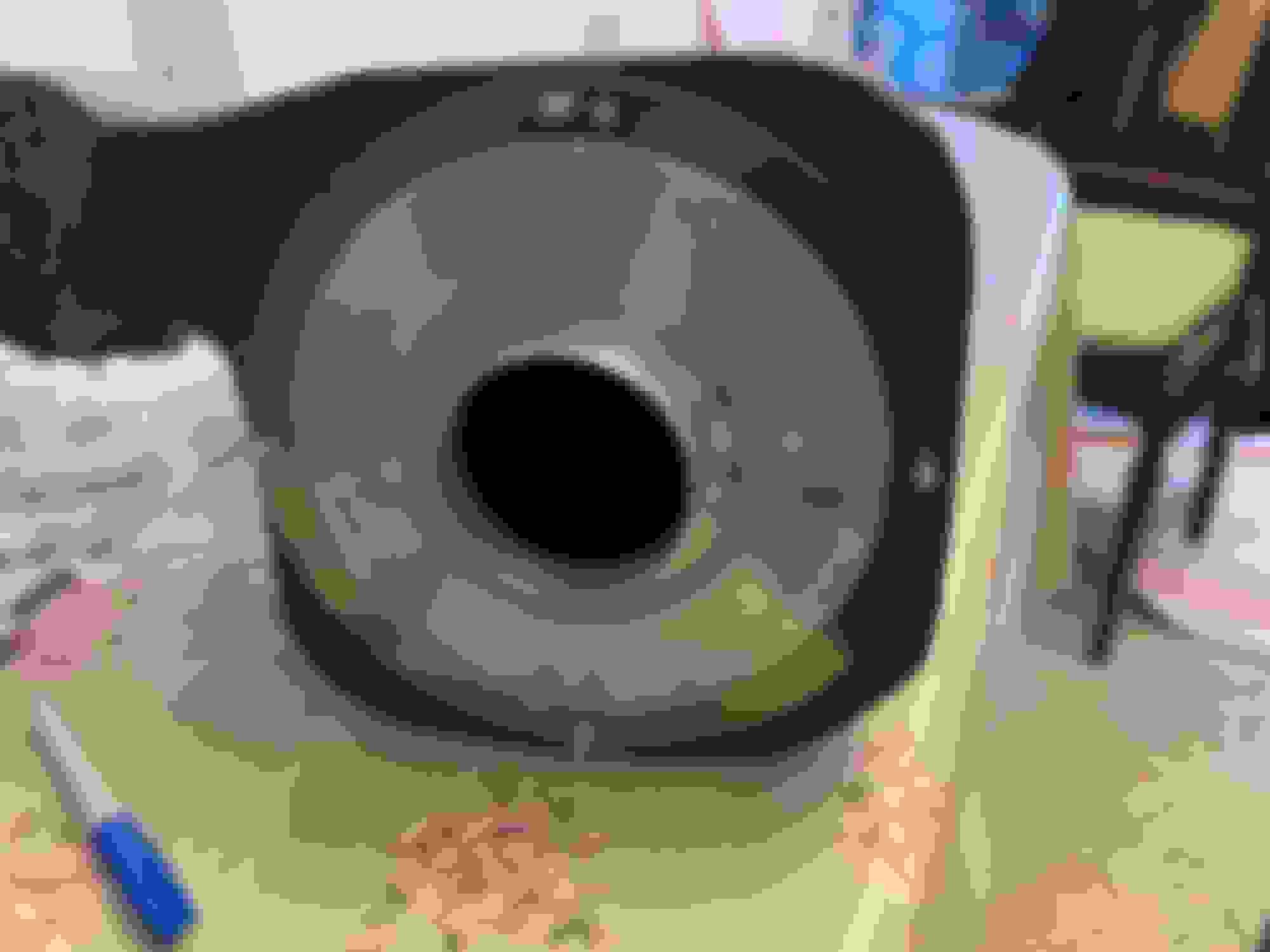
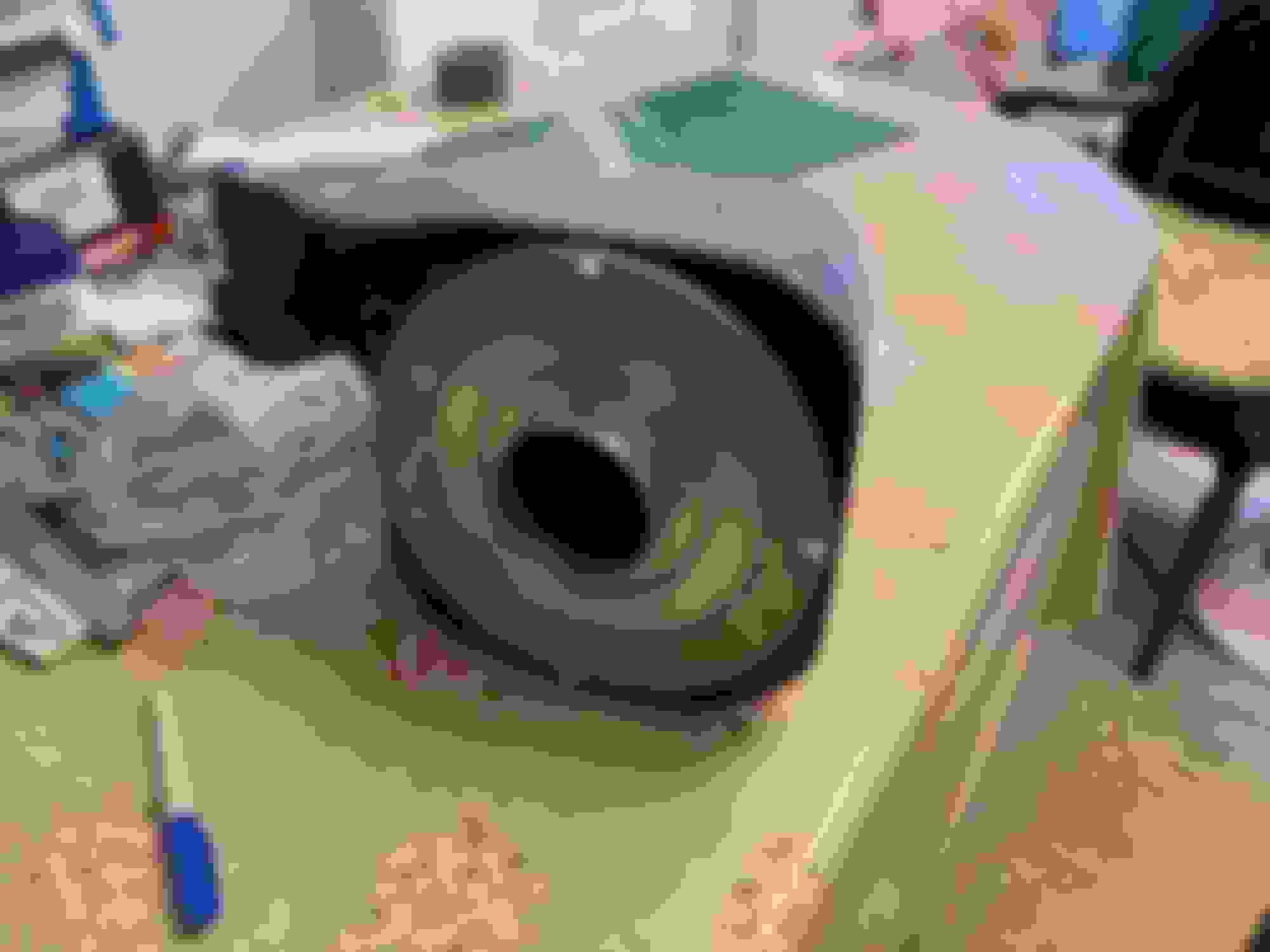
I had three aluminium rings laser cut, I drilled 4 holes around them and clamped one of them to the airbox. I drilled through the box in the location of the holes and marked out the big hole in the centre for the filter.
I then cut the hole in the air box out with an angle grinder and thin slitting disk, which was a bit nerve wracking but worked fine.
One of the disks is a slightly smaller diameter than the filter end, so provides a stop, then there is a disk that is just slightly larger diameter that sits around the filter end that locates it up, down, side to side. The disk nearer us has tapped holes, so the inner disk is sandwiched by the bolts from the inside against the body of the box.
This shows the filter in place, I was a bit smug at this point
then the third disk is smaller diameter than the filter end and sandwiches it all together with the nuts on the ends of the bolts.
really happy with the filter positioning, nice air gap all around the filter to the body
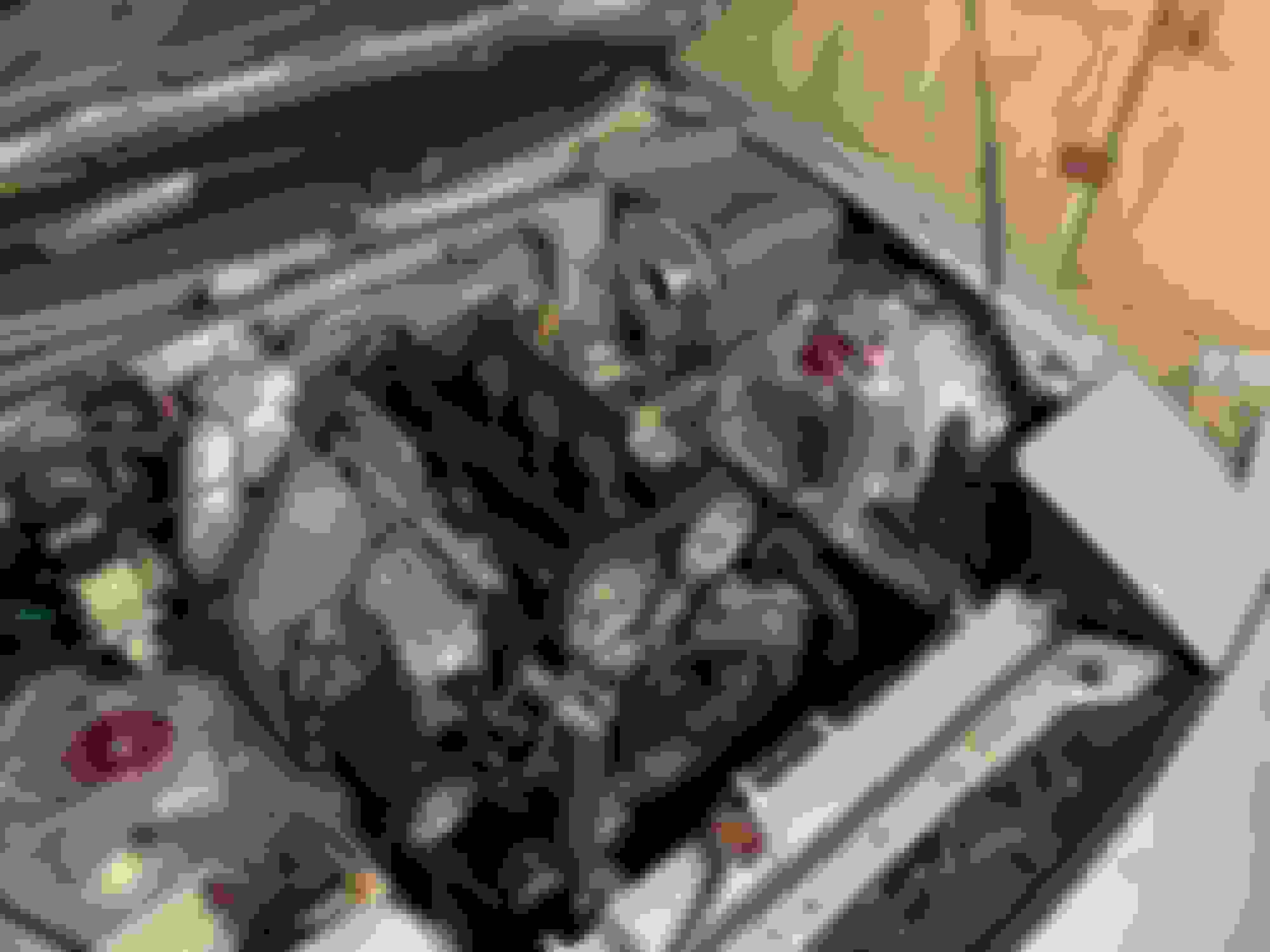
And then in the car. It allowed me to work out what silicone bends I need to change in my current intake tract. It all looks good, far enough away from the exhaust etc,
So i need to make the mount brackets, and get sanding as you could probably tell some parts are aabsolutely cacked in resin
 12-10-2021, 04:59 PM


 2
2


 I cut the cowl about 1cm larger than the intake neck, as I am going to use rubber seal on the edge and this needs a bit of space.