When you click on links to various merchants on this site and make a purchase, this can result in this site earning a commission. Affiliate programs and affiliations include, but are not limited to, the eBay Partner Network.
Engine Sim is a decent tool; the FSAE team has been using that with success before transitioning to Ricardo Wave back in 2007-8. How did you manage to get a free version for a 4-cyl though? Last time I checked the free version supported only 1-cyl models. I believe you will need to add a 2nd intake valve, exhaust valve, and runners to each cylinder, before joining at the plenum. I think you also need a throttle element on the intake side. You can also add all exhaust elements (mufflers, bends etc).
They must have just updated the version you can download, because no trickery was involved.
The ports have the option to say how many valves. So although it looks like a 2valve head in the picture it is actually 4valve in the settings. You are right about the throttle and mufflers, this sim was setup with 1atm boundary conditions, straight into an induction pipe into the plenum. I'm just stepping through it adding a bit more complexity each time, so if I get errors I know it is only an isolated area that has changed. This is the first time in about 10years I've even touched CFD so I'm taking it slow.
Frustratingly on my latest model where I have been trying to add the supercharger I keep getting 'Floating Point Exception' errors, at the same point each time in the calculation, 0041a56. Not the foggiest how I go in and find what the issue is. I can run the sim, with literally the only change being a pipe instead of the supercharger, everything else the same. All settings in the supercharger seem to be reasonable. No zeros anywhere or settings out of proper range that I can see. I'll keep bashing away.
I did a cam plot of both stock BP5A and BP4W cams, and my custom cams so I can use those in my analysis. I have also calculated the flow coefficients of the stock BP4W ports and Na8cgee's fully ported big valve head (thanks Na8cgee if you ever read this) from over on Nutz so I have that input data for the model too. When I have my bench up and running I can update as appropriate. I'm sure its going to be a long road to finesse but gives me something to play about with.
Cool that they do that! Your post actually motivated me to download the latest version and play a bit over the weekend. Na8cgee had done some great work; I have actually reposted his work in here somewhere. Looking forward to your findings!
Cool that they do that! Your post actually motivated me to download the latest version and play a bit over the weekend. Na8cgee had done some great work; I have actually reposted his work in here somewhere. Looking forward to your findings!
Ha ha have fun! I got the supercharger working (although I still don't know why there was an issue) and have a model that produces a pretty representative torque curve and power level.
Yes it was your copied thread that alerted me to his work, very methodical, very impressive.
His goals are slightly different to mine in terms of rev band so I'm not going to wholesale copy, but the level of information provided certainly gives some good hints and tips, along with really good data to start simulating from.
Key thing for me is wrapping my head around how more flow can be extracted from the head but with pretty minimal cross sectional area increases, in an attempt to keep the power band where it is but just make it easier for the engine to injest the air, leaving mean gas velocities where they are. I think the way to do this is to keep an eye on my discharge / flow coefficients and not just let CFM rule the roost. I am treating it with NA tuning concepts, even if the supercharger would / could / may take the spikyness out of a more extreme concept.
Interesting my computer model didn't care too much for port size, or more accurately valve size increase, but it loved a 10mm, short duration but fast lift (lots of area under the curve) intake cam.
Plenty to fiddle with and when I get some good data and half believable results I'll post them up.
I've continued to play around with the simulation.
I dialled in the power figures pretty closely to the setup as dynod the first time last year, so no fancy 8 rib pulleys and the old smaller exhaust setup. This netted 253whp at about 10psi. I did this because I have the full power and torque data, and it was making good power per psi at this point, if that makes sense. I thought it would be easier and more accurate for me to try to shoot for this stage of the build as my baseline than trying to model a stock NA BP4W, which I don't have full data from and that also doesn't really carry a lot over to the build.
Still getting the torque curve right - basically it seems to makes a more torque at 4krpm than it does in real life, but the other rpms are pretty close and representative. Interestingly this is only the case for the new pulleys - must be a quirk in the supercharger efficiency vs engine efficiency I need to work out.
But I think the model is getting accurate enough to demonstrate some interesting points.
1) If you remember back last year when I did the second day of dyno testing with the smaller pulleys, I was very disappointed with how they performed. They didn't add any top end hp. I was still at about 255whp, despite an extra 4psi of boost. This day the weather was absolutely baking hot, well over 30degC. When I ran a simulation of the old pulleys at 20degC, and the new pulleys at 35degC, the simulation showed the same results I saw in reality. A small gain in low to midrange torque but then basically coming to the same peak hp number.
When I run both old and new pulleys both at 20degC the new pulleys make the power I was expecting to see on the dyno.
2) Power figures in the sim are currently more reactive to exhaust changes than intake. I haven't yet seen the gain I expected to see by dropping the PR with a better intake flow (reduced sc drive requirement, increased sc volumetric efficiency). I'm not sure if this is because I haven't got the sim right or if there is some other thermodynamic effect occuring to counteract this gain.
3) Intake pressure at the back of the sc makes a huge difference. I hadn't credited it with the importance it deserved. From my logs the pressure at the back of the sc decreases by about 1Kpa per 1krpm above 3krpm. Didn't really think this was a big deal but the sim says otherwise. There's more gain in removing this slight vacuum than there is in all the headwork.
Power figures are almost there - a little high for whp, but a fair bit lower than the crank hp figures from my dyno days last year. But its really the comparison I am interested in.
I need to find what the restriction is in the system, to design it out. Previously I have tested the pressure in the air filter to throttle body, which shows the 1KPa per 1000rpm drop I modelled. When I have used pressure drop calculators for my estimated flow rate at the inside diameter of the intake tract on its own pressure drop was negligible. Then downstream of that the sc intake / throttle assy and that didn't show any real additional pressure drop (under 0.5KPa total by redline). So this points towards the filter / airbox / cowl duct.
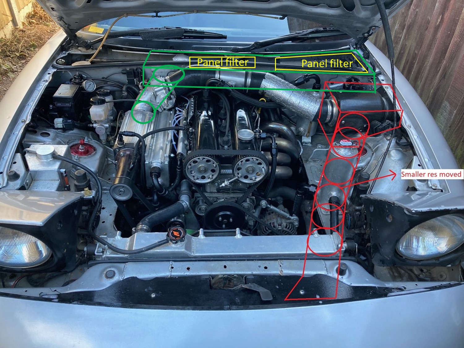
The airbox and cowl duct was designed around my old M45 setup, so was pushed really tightly over to the side of the engine bay, with a tight 90deg into the cowl.
The filter itself is a good quality foam unit, but rated for 300bhp, so I am on the limit of this / aim to exceed this. I need to run a filter, keeping stones out the supercharger > 10hp.
I think maybe a redesign of the airbox / filter and feed it from the nose of the car with a big diameter intake duct is on the cards. I would need to do something with the chargecooler res, to move it out the obvious route for the intake duct, and make an adapter to get the air over the radiators but I don't think that will be an issue. I don't need a chargecooler res that big anyway, and I'm sure the chargecooler system doesn't need all that coolant capacity.
Front feeding the airbox could allow me to pick up some positive pressure on the move to atleast overcome any filter restrictions.
Seems a bit silly to embark on a big cylinder head project without trying to optimise the basics first.
I would be very keen on cutting a hole in the firewall and turn the cowl into a large airbox feeding straight to the SC inlet (given that this is a known high-pressure area). The hole would most probably need to be oval in order to pack the area needed and not feed from the bottom of the cowl, where it would also pick water. You need to find a way to manage water drain from this area (maybe a sheetmetal airbox fitting tightly within the cowl?) and also a way to add a filter (I recently saw a Toyota OEM panel filter that would fit on the far left side of the cowl almost perfectly, cannot recall the model though).
Thanks Harry. I do like your suggestion - positives are minimum length of pipework, big filter area, air draw from positive pressure area maximum noise :-)
There are a few things I think would be tricky but not impossible to implement (water drainage, air tight fabrication) but the main issue is actually being able to orientate the throttle body that angle and fit it between the sc and the bulkhead, let alone giving it room to flex to account for engine movement. You can't see in the pictures but I'm not joking when I say that is the only place / angle / orientation the throttle body can be at sensibly and give room for the tps, idle valve, bypass pipework, brake booster, fuel and water lines and maintain a decent flow path diffusing across as much of the back of the charger as possible. It was basically a happy coincidence that it pointed nicely above the coil packs because it was the only way it was going to fit.
I thought about making a larger airbox in the current location, but take air from the cowl more centrally, with a bigger overall opening. This would allow me to run a bigger filter, in the current location, because I don't need to leave room for the 90deg silicone bend I currently have tucked under the wing flange. It would keep pipework the same length, but with a bigger opening into the cowl in a slightly better (more central) location than I have now. The only thing I have against this idea is how to protect against the engine tearing the airbox apart when it moves. I get around this with the current setup by soft-mounting the air box on rubber isolators, and the 90deg silicone bend to the cowl also allows the air box to move with the engine a bit. The air tract over the top of the engine doesn't have a lot of give. I don't want to go to a corrugated flexy duct because it will play havoc with the air flow. So the new box would have to also be soft-mount and that might be more difficult going to an 'odd' shaped intake through the cowl, rather than the current round one. If I could get around that it would be really neat.
I'm not 100% sold on the front feed idea, namely because of the additional length of pipework, and I think when I look at it the 'make an adapter for over the rads' is going to be trickier than I credit it with now. But it is also one (the?) highest pressure area on the car to draw air from.
I went out for a little drive this morning to get some logs. As per usual there were some issues.
AFR gauge was playing up again, same issue as before. Flicking to full lean fairly randomly. The only pattern it really followed was it would go full lean on WOT. But in reality the car was definitely not full lean. No misfires etc that would indicate the reading was correct. It would also go full lean at other random times cruising too. I can't hear any exhaust leaks, the last sensor lasted since March in the position on the manifold. I'm a bit loathe to just buy another sensor. I know the map is good so I'm going to switch fuel control off the sensor for now while I research.
The car still just feels a little lacking in the trouser department in comparison to how it was. It's still quick but it just doesn't quite have the old urge it had. I did a quick virtual dyno and it agrees - peak torque down to about 207lbft at a slightly lower 5000rpm. Torque at 6700rpm down to about 185lbft. This is down about 15-20lbft across the board on where my testing indicated the car was pre rebuild. Leak down tests have been perfect, and I will compression test it. There's nothing silly like the brakes binding as far as I can tell. I know this stock BP4W is not skimmed at all so compression should be stock 9:1, whereas my last head had a fairly healthy skim so would be 9.3-9.5:1. But 15-20lbft seems like a little unrealistic for such a small change in comp. Bit fcked off with it if I'm honest. Maybe it also needs another degree of timing because the comp is slightly lower. Not sure but I will work through it.
It has been interesting to see the difference in terms of MAP between the two heads -
Fainter traces are the old head. MAP is sort of magnified here, bottom of the graph is 170kPa. You can see boost is lower in the midrange on the stock head, indicating better flow, but then in the higher rpms boost rises. My old head had more boost (restriction) at low / mid rpm but then breathed better in the top end. You can also see that the rpm trace for the old head is steeper, indicating more acceleration and more power. Both these tests were done on the same bit of road, same gear, roughly same fuel level.
I started testing the air intake pressures / feed locations. I tested air pressures at three different locations on the car, in the airbox in front of the filter, in the cowl area in front of the windscreen and in front of the radiator.
First up the airbox, in front of the filter. This showed a definite trend of dropping pressure with WOT / rpm increasing, but maxing out at about 1kPa by 6700rpm. So this basically shows the majority of the pressure drop in the intake system is caused by the filter. Downstream of the filter I see a drop of about 6kPa at 6700rpm - so the filter is responsible for 5kPa of that drop. As I was revving the engine up to 7700rpm on the old head my actual maximum pressure drop will be higher than that. I feel like I want to do a couple of power runs on a dyno somewhere to do a cool temperature test with the current intake setup, then remove it and do a run bare throttle body to see if I see the gain that the simulation and logic dictates I should see, before I spend money on making new airboxes and buying new filters etc. I'm still conscious that the last time I tested (on a very hot day) I did not see a proper gain (+2hp). But first I want to sort the AFR readings and compression etc.
In my testing this morning both the cowl and radiator area showed roughly the same results as one another. Possibly a small pressure increase with speed, although so small it was hard to see a trend within the normal variation of the sensor just sat still. We are talking well under 1kPa. Certainly no loss in pressure in both locations though which is good. I think I probably need to refine the test technique a little.
Popped over to a mates to do a warm compression test. Really pleased with the results, although it obviously doesn't explain the power loss.
Basically 15bar / 217psi across all cylinders. Lowest was 14.8, highest was 15.2. Well chuffed at that, both in terms of total number and consistency across all four.
So cylinder sealing certainly does not appear to be an issue, and it has a few hundred miles on it and the dipstick is still at full.
I am going to check / replace the bypass valve, but it might be that it needs a little bump in spark timing. I'm going to take a look in the simulation to see if I can spot anything too.
Interestingly it sort of feels stronger without the water injection on. I have backed it out a bit but I think I am going to test a run without it spraying to see if that is a cause. Maybe the small drop in comp has tipped a balance there.
I have a theory with the AFR sensor too. Currently the live is connected to the fuel injection feed, so it comes on with ignition on. This morning I was sat with ignition on but engine not running for a little while while I fiddled with some settings. I wonder if the car then being cold started with a fully warm sensor is what damaged the latest sensor. Apparently this is meant to be quite bad for them. I am going to replace the sensor and make it so the gauge only runs when the engine is running, and see how that goes.
I don't think it is a wiring issue because it seems to fully lean out when flow rates in the exhaust increase, almost like it is overwhelmed by the increased gas and heat, now it has been possibly damaged.
I did some further investigation on my power run from yesterday and it looks like for some reason the WI system was spraying more than it should. It was spraying around 35-40% water to fuel in the low to midrange, which won't help anything. It was still proportioning but just looks like those low and mid rates particularly were higher than they should be. Needs investigation.
Also I tried to analyse optimum spark timing. Interestingly the simulator said there was not a requirement to advance spark at lower comp. However I compared EGTs between my Llandow trackday (old higher comp) and Anglesey (new lower comp). The trend was EGTs were around 40-50degC higher at Anglesey, suggesting a later combustion event, that may need to be compensated for with an extra degree or so of timing.
So plan is to get a WI off test run in to see where we are and eliminate WI from the equation, then give it an extra degree of timing and see if it makes any difference.
I did expect it to be a little down on torque, by virtue of the drop in comp, but more like 5lbft not 15-20lbft. I really want to be making about 220lbft peak torque and 205lbft at the current redline to get back on par with where I think the setup in it's current form should be.
I went out and did some testing, without spraying the water. The car is faster without the water injection currently. The butt-dyno, rpm gradient in the datalogs, and virtual dyno all agree. More faded traces are with WI on, more solid traces are WI off.
Data above is on exactly the same bit of road, and if anything the non WI run was done at slightly higher ambient temperatures. With WI off I am about 0.5secs faster to get to the top of this gear, which is fairly significant.
Interestingly note the reduced rise in MAT with WI on compared to off.
The non WI virtual dyno pull came out a bit odd around peak torque but upper rpm areas look about right, 259whp @6814rpm. As normal peak torque doesn't calculate correctly as it is about 208lbft at 6814, when really it should be about 200lbft for that hp - but regardless the data shows its making roughly the power it should with the WI off, so I am happy with that.
Bit odd around peak tq but generally speaking shows there isn't anything wrong with the car with the WI off
Adding another degree of timing didn't gain me anything visible in the logs or virtual dyno so I will keep the timing where it is.
I checked again my WI flow rates on the drive and they are still too high through the midrange, despite not having changed the PWM settings from when they were good.
I'm going to check the system out. Might be my JB weld restrictor has been eroded slightly. I will get it back into line and do another power comparison.
It also might be that at what is meant to be 9:1 on the stock head the CR just isn't there to take a power benefit from it. Something to think about for the next head for sure.
I've booked a few power runs on a dyno end of this month to get a baseline of where we are right now.
Hopefully its not a massive disappointment.
Pre rebuild I thought I was peaking at mid 280 to 290whp @ 7400-7500rpm with WI on and the old head with the skim.
Taking into account the slightly lower comp and that water injection seems to hindering rather than helping currently I am hoping for peak torque 220-230lbft, 265-270whp peak power.
It will be a colder day than my last dyno session, which will help. I have the bigger exhaust also. I will be down about 0.5CR but the engine is nice and fresh.
I want to test without WI, with and without intake tract to see if the filter restriction is causing the power drop I see in my simulations.
I may test with / without water injection if I can get it proportioning properly again.
Just want an accurate baseline in controlled conditions to work from over the winter.
I tested running a degree more timing without WI and with the lower comp and it didn't result in any gains.
I can see there is something up with the WI currently, so that needs to be resolved first before I play with timing. It may return to being a benefit once sorted, but at the moment you can feel and see the difference in the logs. But yes, maybe it does need a bit more timing at this lower CR with WI when corrected to a reasonable flow rate.
The gains in the simulation in order of size are:
> Lower intake restriction - I can test this best on the dyno, should be simple to establish if gains are on the table. I will take a bellmouth with me to attach to the tb to give the best case flow possible.
> Compression ratio - Easy win really, pretty comfortable that I can safely bump this up to about 10CR, particularly with the WI on.
> Head porting - small gains on the exhaust. Sim doesn't reckon much of the intake side of things.
Then there is the gain from the intake porting that does not appear in the simulation, lowering the PR, increasing the mass flow rate and lowering the drive requirement to gain approx 6hp per 0.1PR drop.
I already have 90% the parts for the head, most just carries over from the old head. But it is very time heavy, building and testing on the flow bench required to ensure any more adventurous intake porting is even across all cylinders. I think it is worth a crack.
Compression ratio is a �50 skim and a head gasket, that is going to get done regardless.
Intake optimisation is the more expensive one and quite time consuming but also the easiest one to see what the benefits could be before doing the work.
More than enough to keep me occupied don't worry, you won't see any extra cylinders or dry sumps poking their head up
stupid question maybe, wouldn't you gain more with exhaust port work as theres fi?
Rich.
On the simulation for my setup at my flow rates the sim reckons there is a bit just over +5hp to be won going to a +1 exhaust valve and associated porting, but it is all above peak torque.
Running the sim for +2 exhaust didn't get me anything further at my power level.
Sim reckons +1 intake and porting is good for +3hp by redline again all above peak tq. But I did some calcs a few posts ago that suggested there could be bigger gains from increasing supercharger efficiency with the lower PR a better flowing intake enables. I am conscious that Lotus knows an awful lot more than me so my calcs may be a red Herring, not sure.
Honestly, I am on the fence about going full ***** on the head. I want to do it for the experimentation more than anything, but another part of me says I should just chill. On the other hand when combined with the other hopeful gains through compression and intake optimisation it ends up as quite a big carrot.
I do want to get my custom cams back in the car though, and bump the compression. I'm pretty sure it is these two factors that just mean the car still lacks a little of the high rpm sparkle it did have pre rebuild, that made it so fun to drive.
Originally Posted by Zed.
wuss
I'm goin Vauxhall.....
Rich.
Now now hopefully the car will survive plenty more winters - plenty of project creep left in her yet.
Ha ha I need to catch up on your build actually. What was the kicker? Just a way easier bump in performance?
[QUOTE=Tchaps;1610770]Now now hopefully the car will survive plenty more winters - plenty of project creep left in her yet/QUOTE]
but have you had any silly ideas lately?
maybe they're due
Originally Posted by Tchaps
What was the kicker? Just a way easier bump in performance?
erm, to build the Mazda 1.6 involves large financial outlay & guesstemation / development...
also I have a few 20XE engines already - one drysumpped etc so strong & reliable power for minimal conversion spending
standard 20XE on decent management / de-restricted is 200hp with ~240hp available from cams & pistons (300 if you've the cash and new / improved heads & alloy blocks now being made to replace the standard iron blocks)
only downside is being evicted from 1600cc capacity classes and out with the BIGBOYS, where theres plenty of Millington Diamond engines with ~350hp in NA
suppose someone's got to finish last (OR be the fastest to the scene of the accident)
Now now hopefully the car will survive plenty more winters - plenty of project creep left in her yet/QUOTE]
but have you had any silly ideas lately?
maybe they're due
Rich.
Ha ha always. I think of drysumps before I go to bed and carbon kevlar as I wake in the morning.
What can you bore them out to? It is mad that they can make the same power I am looking to make NA. I know the Millington's specifically have atleast 0.5litres on me but still. Pretty mad.
Ha ha always. I think of drysumps before I go to bed and carbon kevlar as I wake in the morning.
perv
do it
Originally Posted by Tchaps
What can you bore them out to? It is mad that they can make the same power I am looking to make NA. I know the Millington's specifically have atleast 0.5litres on me but still. Pretty mad.
xe's can do 2.5L with work but overbore to 2.1L reliably. theres a modern 2.2L ecotec (x22xev??? Vauxhall / GM) crank that fits the XE block as it's the modern emmisions evolution of the 20XE.
Cosworth had a hand in the head design of the origonal XE, the ecotech that followed was more emissions orientated design & doesn't produce great power...
subject of Cosworth, the Millington Diamond is a re-think of the Ford Sierra Cosworth 'YB' 2L but without the turbo, Millington basically kept the head and binned the rest
now evrything is cast / machined and just looks similar when installed....
want 2.8L?
start @ �20,000...... https://www.millingtonengines.co.uk/new-engines/
anothr engine of interest is the old Volvo B23 or B230 in 8v & 16v variants, theres a B23ish 8v locally in a mk2 Escort rallycar that was running ~300hp NA (ok, it was 3L and seriously fettled!)
Yes a regular visitor on the Millington site. I have to put clingfilm on the keyboard to protect from the dribble. Great story of 'man in shed' origins.
Been reading up a bit more on BMEP generally, but came across this thread that I thought was a good easy tool for quick comparisons:
Going by the maths on the thread above on my engine, at peak torque:
(220lbft / 1.884L) * 2.47 = 288.4psi
288.4 / 2atm = 144.2psi/atm
Quite a long way short of the 180psi/atm BMEP target. I am pretty sure I am not short on timing, given my testing so far, but I think it shows that I am leaving a bit on the table in other areas.
If I run the sums on what the simulator says I could achieve with my intended modifications
 10-01-2021, 05:03 AM


 0
0