
f20c engine conversion


Oh.. and more of this..
 I love this build.
Reply
 0
0

0

Iv used it on K series and its always been cake, but maybe hondata hasnt worked out some issues with the ap1/2 yet.
AEM is great too, just not quite as simple to setup as Hondata, which is why I asked.
Reply
0
0

I know this is a newb question but what purpose/benefit do the cut out holes in the rear bumper provide? I know it has to be for aerodynamic purposes but I never have understood the principles there. Anyone care to elaborate?
Build is Sick!!! Wish I could drop my K in my Miata.

Build is Sick!!!
Wish I could drop my K in my Miata.
Reply
0
0

I know this is a newb question but what purpose/benefit do the cut out holes in the rear bumper provide? I know it has to be for aerodynamic purposes but I never have understood the principles there. Anyone care to elaborate?
Build is Sick!!! Wish I could drop my K in my Miata.
Build is Sick!!!
Wish I could drop my K in my Miata.I had that plate (built years ago for drag hondas as a trim piece for clean bumper cutting) and just decided to toss it on the car.
Reply
0
0
I'm still confused...are you saying it's a literal parachute that pops out and slows you down or it acts as one? I think you're saying the ladder and if thats the case how to those holes help with that effect?
Reply
0
0

actually cutting those holes allows air to go through them. If you just left it stock, air wouldn't flow into your bumper because there would be no where for it to escape through. Instead of flowing beneath your bumper, air actually creates more drag by going through those holes.
Reply
0
0
The theory behind the holes is that it allows the air that gets 'caught' inside the rear bumper to escape. Personally I would have to see wind tunnel data on this sort of thing. Many people do the same thing by removing truck tail gates, but the opposite is true. The air gets trapped in the bed, creates a high pressure bubble of sorts that just swirls around and the free air stream flows over this high pressure area and aerodynamics suffer when the bed is removed. I suspect a similar thing happens with the bumper, but again, it would take CFD or wind tunnel analysis to be 100% sure.
edit: ^^ at least 1 other person agrees and beat me to the punch..
edit: ^^ at least 1 other person agrees and beat me to the punch..
Reply
0
0
Whatever guys... I know people trapping higher MPH at the drag strip solely from rear bumper removal. That is enough for me. It cost me nothing to do.
Back to OPs thread... as talking about rear bumper holes doesn't exactly measure up to talking about a F20C-T miata project.
Back to OPs thread... as talking about rear bumper holes doesn't exactly measure up to talking about a F20C-T miata project.
Reply
0
0

The latest hondata for f series engines requires a change in valve covers to the latest version with only 1 cam sensor. You also need to install a crank shaft position sensor, which is not on the ap1/f20c engine. So that means a new front engine/timing chain cover, all this equates to a big pain in the ***.
Not to mention it is pretty easy to find a used AEM in great condition for half the cost of new. I looked for a used hondata and couldn't find anything.
The guy that is going to tune for me is well versed in both hondata and AEM, he told me that he could get the same performance and safety out of either EMS so I went with what was available; which also happened to be cheaper. Though I don't think 800 for an EMS before adding uego can be called cheap.
Hope this answers the question, and helps with the useless knowledge aspect of this thread. After all this is a Miata site, not a honda site.

Reply
0
0
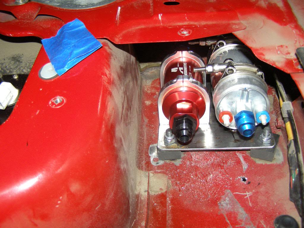
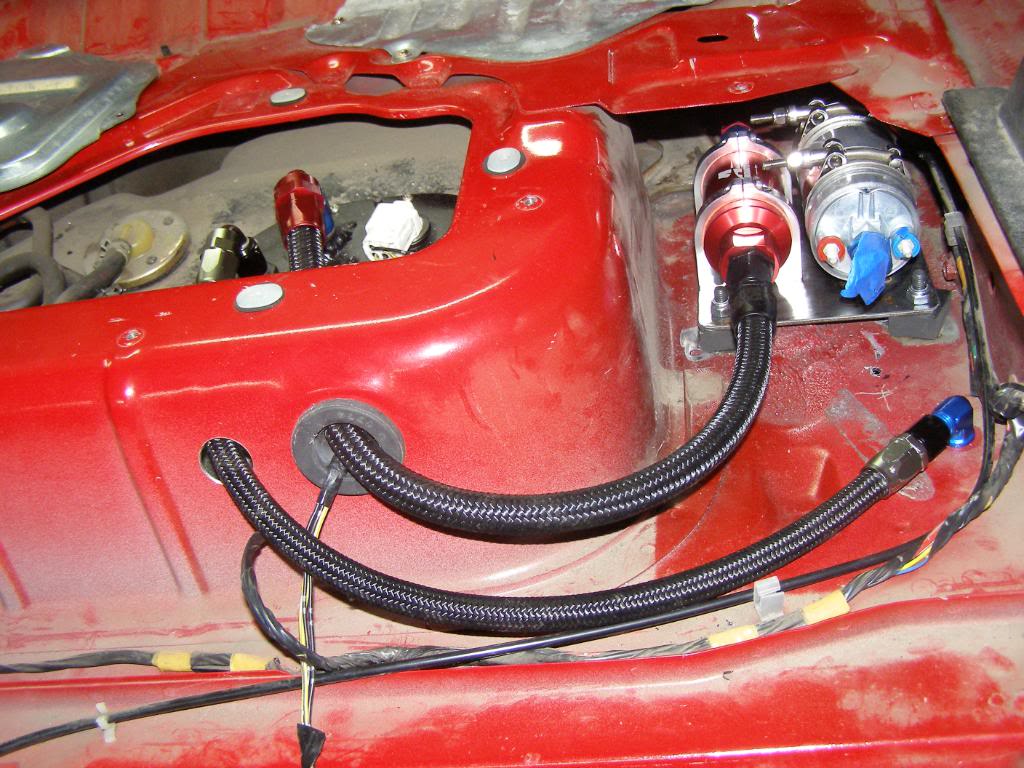
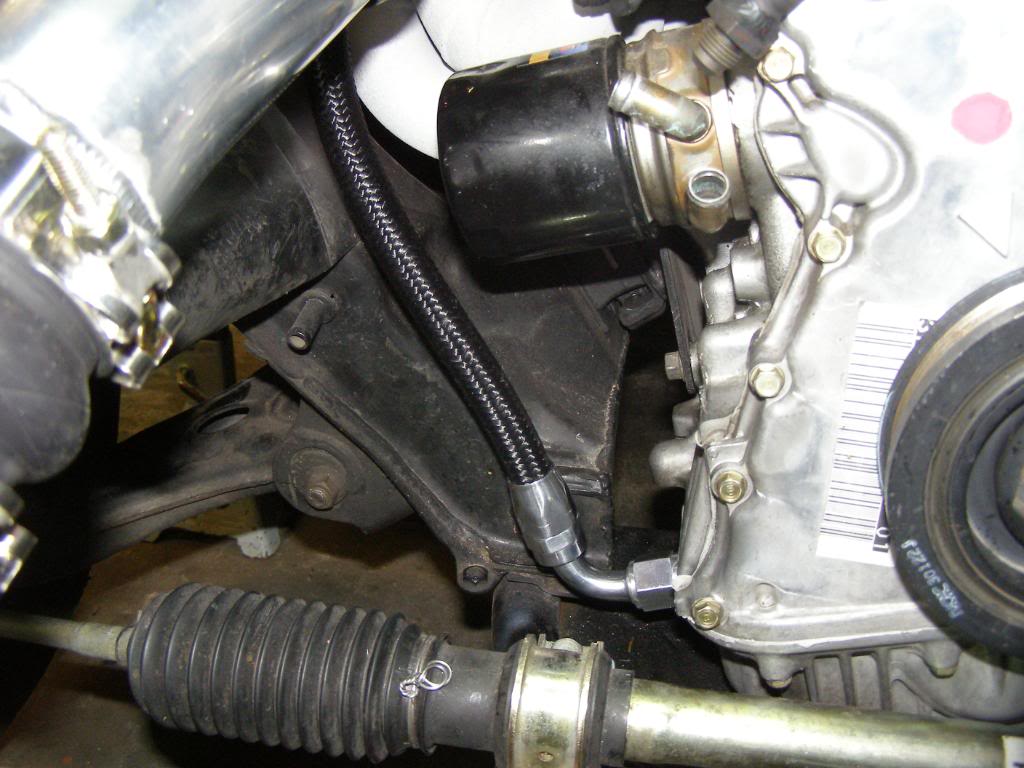
I know that you are all a bunch of picture ******, so here you go. Got some more work done on the fuel system, still need to run the fuel supply and return lines under the car. I need a grommet for the return line through the bulkhead, and I included a couple of pics of the oil return line as well. Oh yeah, don't get to concerned about the different colored fittings, everything under the hood will be color coordinated. Once I button up the supply line, grommet and wiring you will never see these fittings again, so who cares if they match. 
Reply
0
0
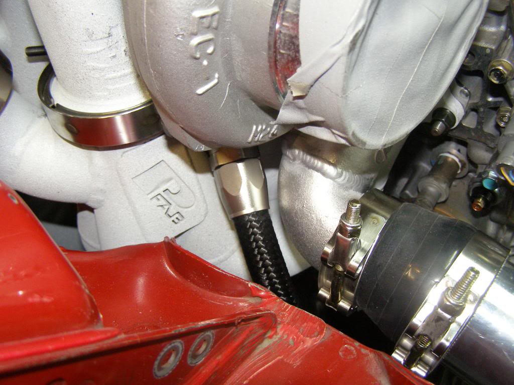
Here is the latest update, I got the coolant lines for the turbo built and installed, also mounted the boost solenoid. I wanted to use hard lines for the coolant lines but I couldn't bend the tubing tight enough; there in not much space between the turbo and the valve cover.
Here are the pictures.
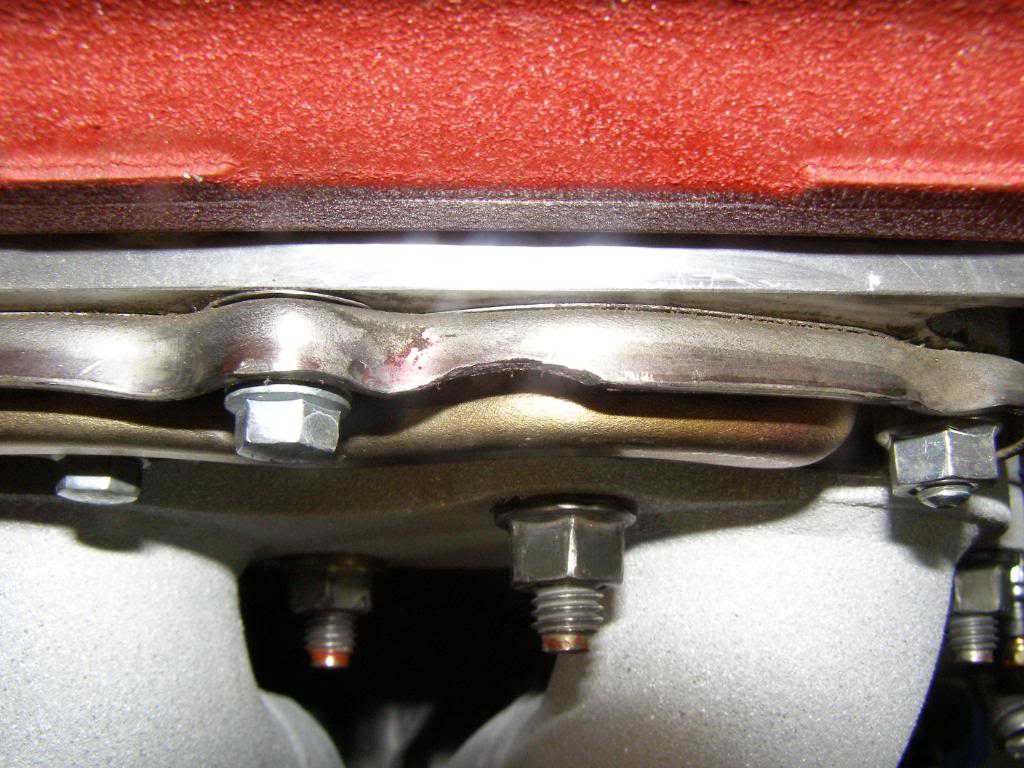
I wasn't kidding about things being tight, I had to grind a little relief in the AIM, (air injection manifold) to create clearance for the coolant feed line. I also had to go with a 120 degree fitting to maximize the clearance between the fitting and AIM.

I know it doesn't look like it but there is actually a decent amount of space between the fitting and the AIM; about 3/16 of an inch.
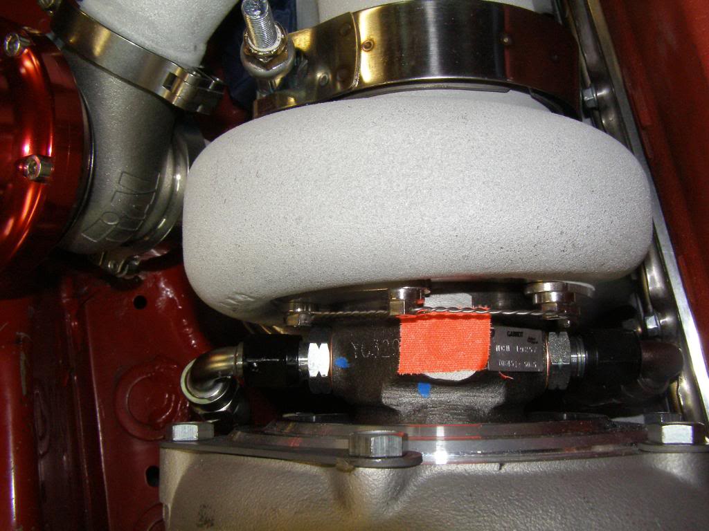
I took this shot to show the fittings for the coolant lines, but what stands out to me is the un-coated WG. I can't believe I forgot to send it in for coating. When I pull the engine out this winter to paint the engine compartment, I will send it in.
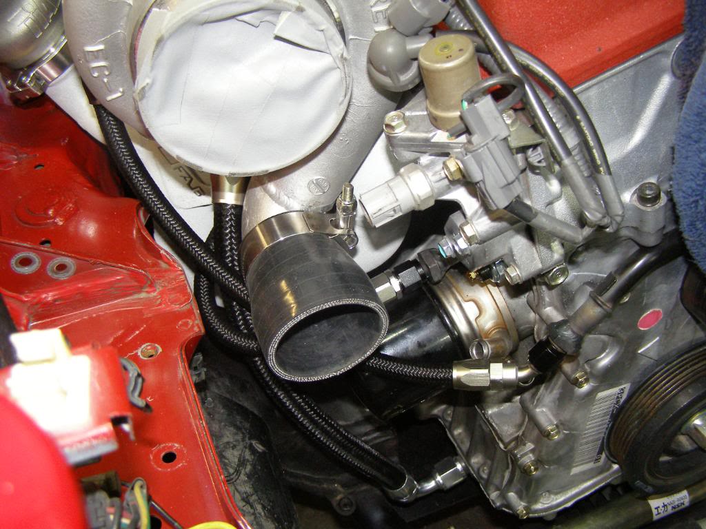
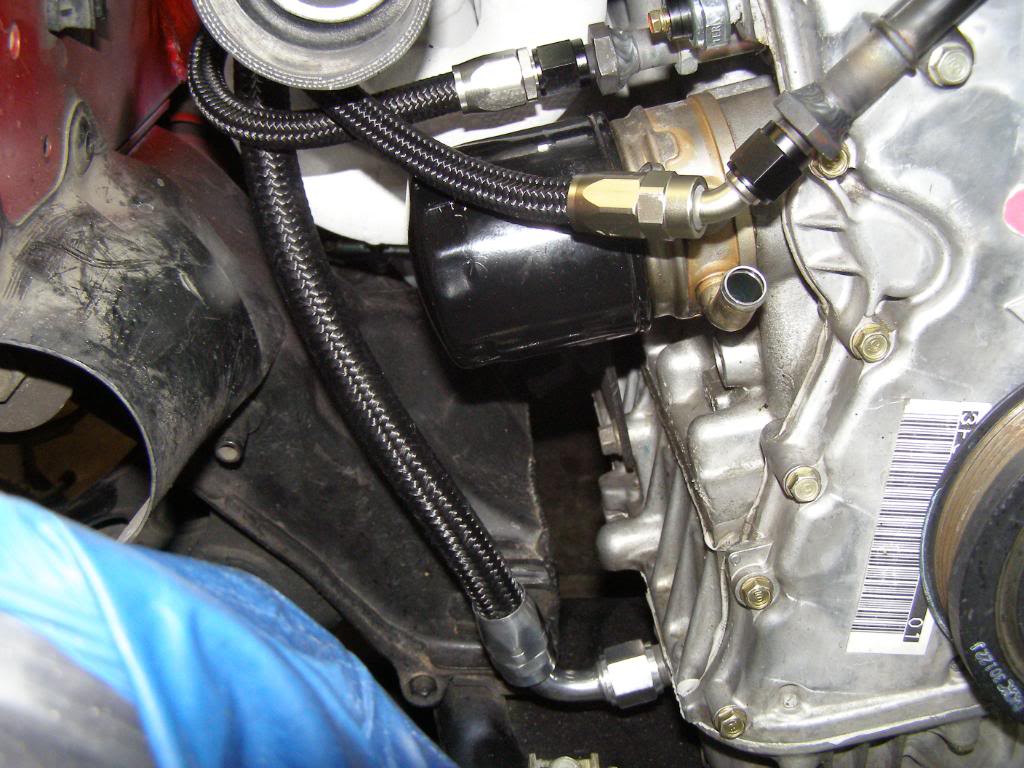
A coupe of pics of the coolant lines and the oil return line.
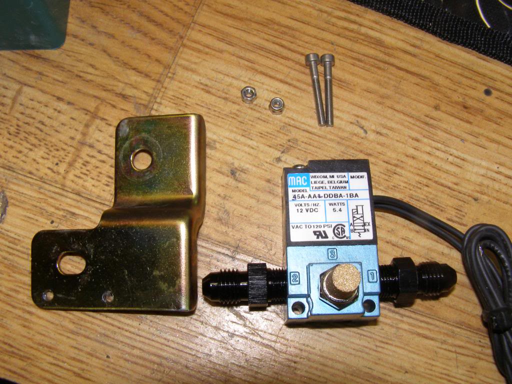
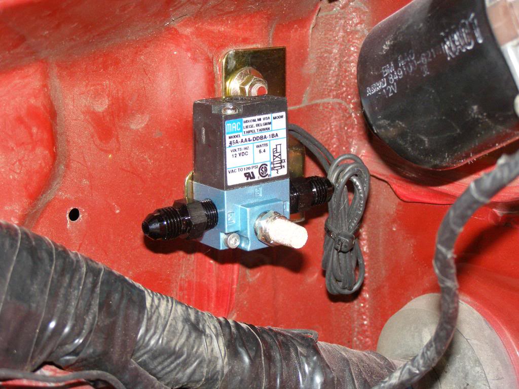
Boost solenoid mounted on passenger fender well.
Here are the pictures.
I wasn't kidding about things being tight, I had to grind a little relief in the AIM, (air injection manifold) to create clearance for the coolant feed line. I also had to go with a 120 degree fitting to maximize the clearance between the fitting and AIM.
I know it doesn't look like it but there is actually a decent amount of space between the fitting and the AIM; about 3/16 of an inch.
I took this shot to show the fittings for the coolant lines, but what stands out to me is the un-coated WG. I can't believe I forgot to send it in for coating. When I pull the engine out this winter to paint the engine compartment, I will send it in.
A coupe of pics of the coolant lines and the oil return line.
Boost solenoid mounted on passenger fender well.
Last edited by hingstonwm; Sep 1, 2010 at 03:40 AM.
Reply
0
0


Junior Member
Joined: Mar 2010
Posts: 413
Total Cats: 2
From: onion city,ca
started reading your build thread at 10 this morning and just finished (after an excursion to the s2k site for the other swap). well executed. very well executed. :kowtow:
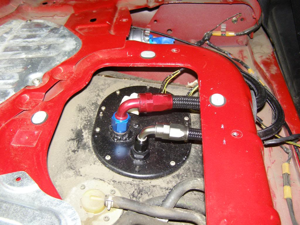
i'm getting tired of gas leaks and was thinking of rigging up fuel with an fittings like you did. this pic caught my eye. looks great. do you have any more details? did u cut and weld an fittings onto the stock lines or run new ones? the stocks are plated mild steel i guess, so curious what fittings you used.
one last question, is there any compelling reason to locate filter where you did? i'm thinking i would like to keep all sources of leaks outside of the cabin... which means under the car right next to the hot exhaust. sigh.

Reply
0
0
started reading your build thread at 10 this morning and just finished (after an excursion to the s2k site for the other swap). well executed. very well executed. :kowtow:
i'm getting tired of gas leaks and was thinking of rigging up fuel with an fittings like you did. this pic caught my eye. looks great. do you have any more details? did u cut and weld an fittings onto the stock lines or run new ones? the stocks are plated mild steel i guess, so curious what fittings you used.
one last question, is there any compelling reason to locate filter where you did? i'm thinking i would like to keep all sources of leaks outside of the cabin... which means under the car right next to the hot exhaust. sigh.
As I said in an earlier post I am running a bosh 044 out of tank pump. I located the pump as close to the tank as possible, in order to minimize the distance the pump needs to pull fuel. Since I am not running an in tank strainer, I mounted the filter between the pump and tank.
I am not concerned about the location of the pump and filter as they are behind the parcel shelf. I plan on putting an on board fire system in the car, one nozzle pointed at the fuel rail and one pointed at the fuel pump/filter assembly, just in case.
The tank access plate is covered in a zinc coating so make sure you sand it off. I used steel, male, AN fittings that are designed to be welded, 4 total, two on each side of the access cover. Check back in a few days for a posted photo, hope this helps.
Last edited by hingstonwm; Sep 2, 2010 at 10:08 PM.
Reply
0
0
Reply
0
0
Why didn't you just use bulkhead fittings? I'd also like to see the in tank shots. Mostly just to see how you did it, seeing as I'll probably never need a fuel system this robust.
Reply
0
0


