
sean's cheap thrills, 90 1.6 with subaru td04

Thread Starter

Joined: Sep 2012
Posts: 4,560
Total Cats: 1,143
From: your mom's house phoenix, AZ
at this point i figure it cant hurt if i do, but if i dont we know what can happen. my latest concern was, do i do all 3 cuts, or just 1 cut between 2 and 3, or 2 cuts between 1 and 2 and 3 and 4 like you suggest. the latter seem most appropriate and popular.
regarding whether to mill flat before or after the relief cuts are made:
if i relive first, then mill flat i run the risk of different flange thicknesses at each port. this becomes a problem on the nuts that will bridge across 2 different port flanges.
if i mill flat first then relieve, then i maintain the stresses perpendicular to the flange mating surface, which really shouldnt be that big of a deal (my assumption anyway). the nuts shoudl pull eberything in line against the head with little problem.
this is of course assuming there are any significant stresses in that direction.
so i think mill first, relief cuts last.
Reply
 0
0

0

With a log I most certainly would. Most of the growth with heat on a log manifold is along the length of the flange, and its going to grow at a different rather than the flange. which is where the warpage comes from. My tubular has way less growth in that direction, it actually moves the towards and away from the block instead. Trust me, I nearly melted my work computer running the simulations.
Reply
0
0
Thread Starter
Joined: Sep 2012
Posts: 4,560
Total Cats: 1,143
From: your mom's house phoenix, AZ
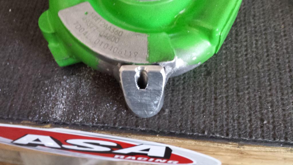
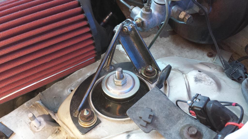
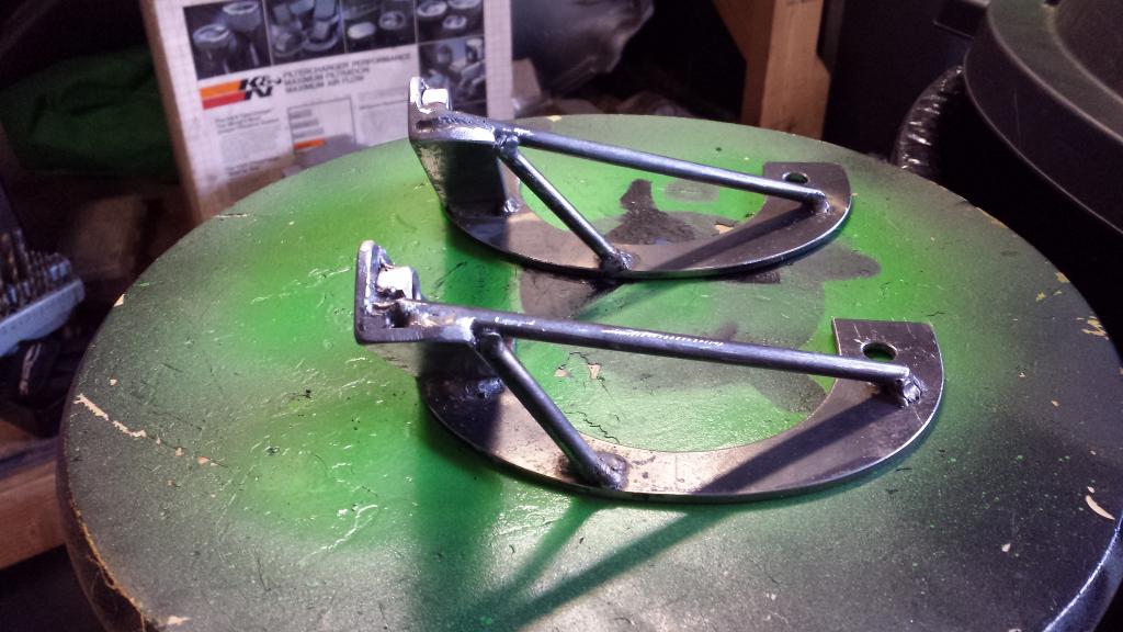
i borrowed and aluminum mig setup and welded a boss on the compressor housing to reclock the actuator
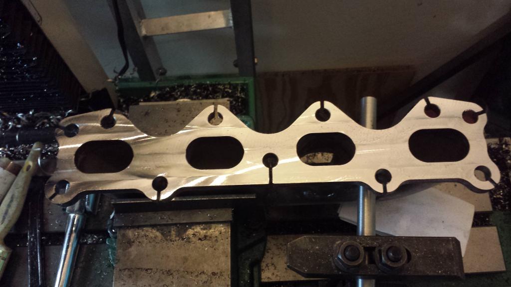
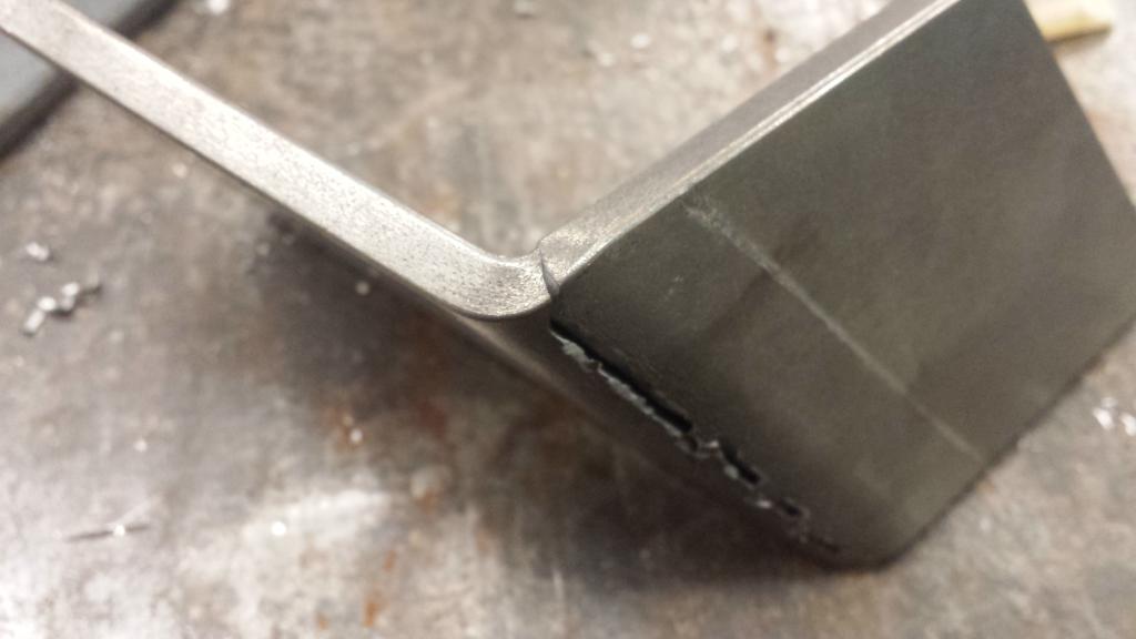
i milled the exhaust mani flat
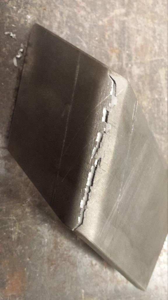
i zeroed out between 2 and 3 and it took this cut. the area above the port is from filing.
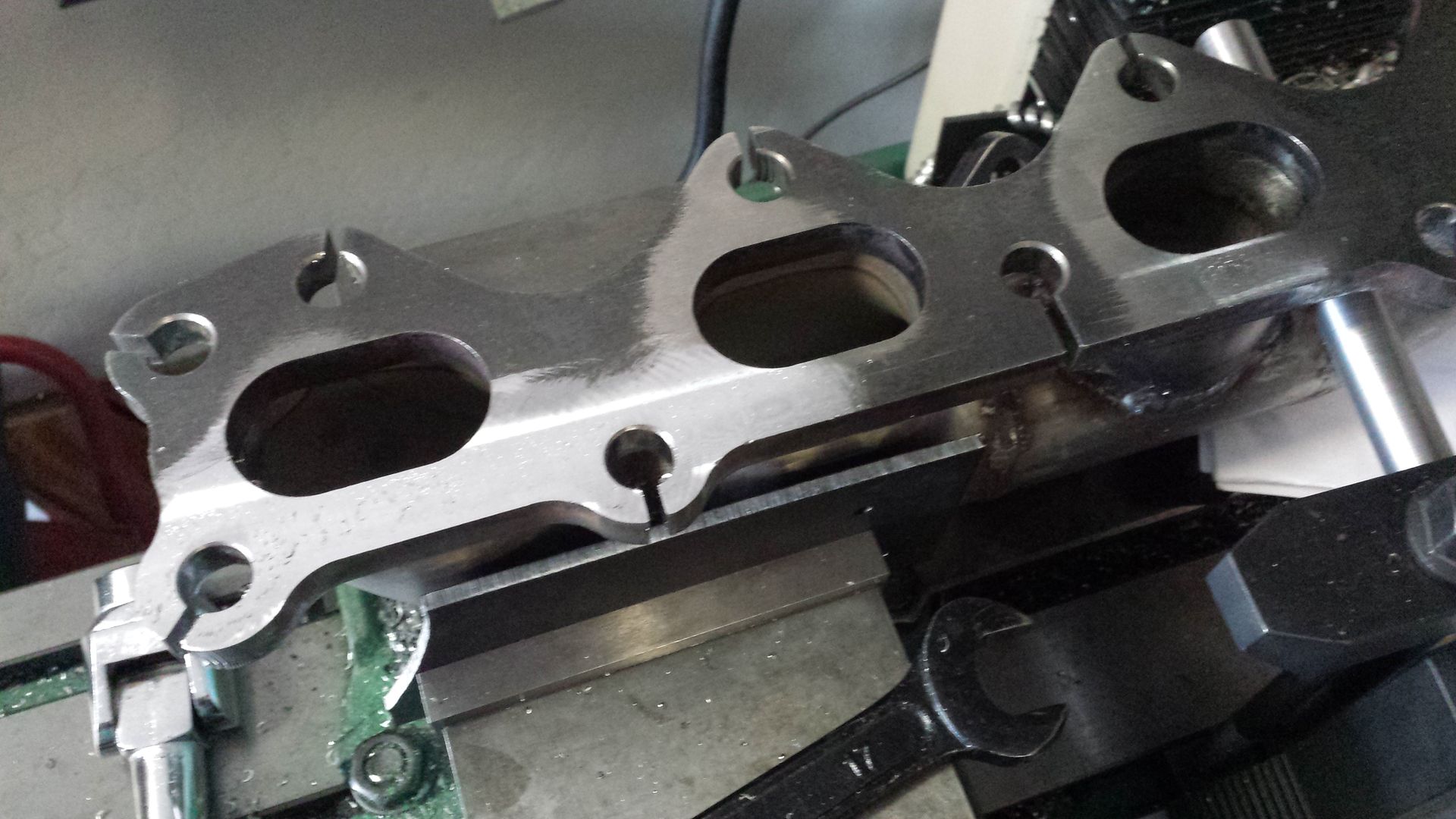
+0.005
+0.0065 and that little corner of the bolt hole above the port is the only thing that is low with some mill scale sill left. done
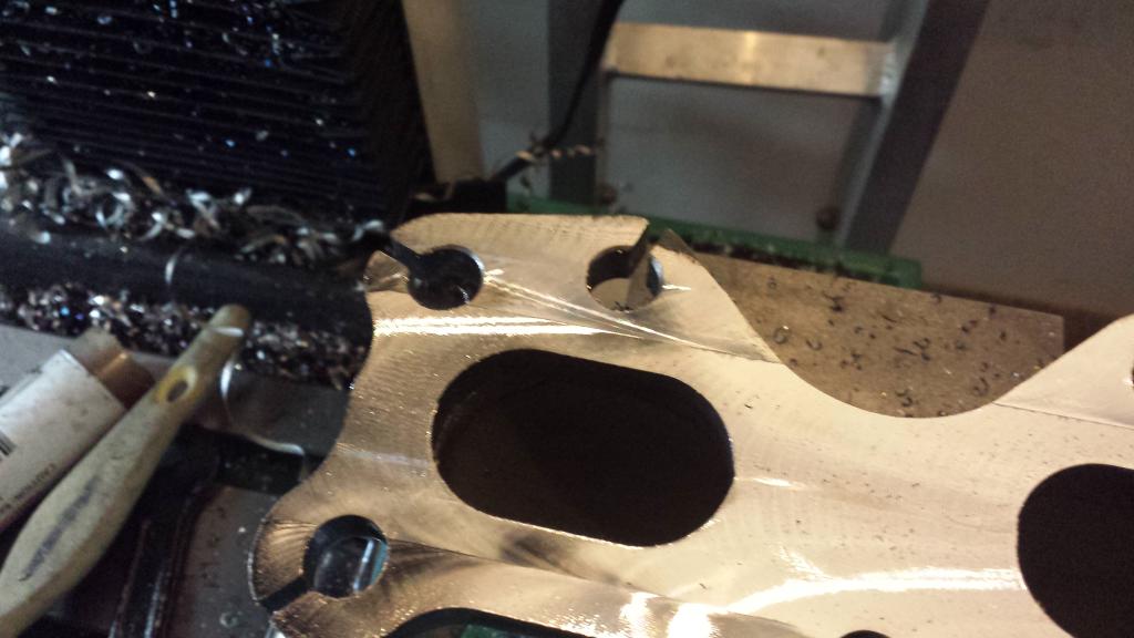
so it was warped by roughly 0.0115"
and here is an artsy whatever closeup picture
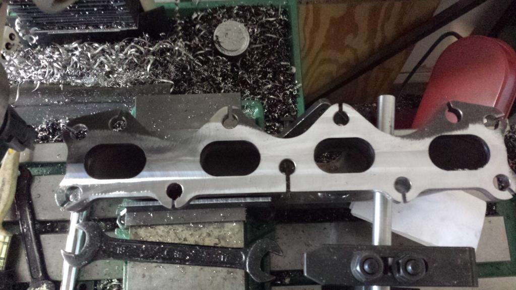
and here is my ridiculous setup
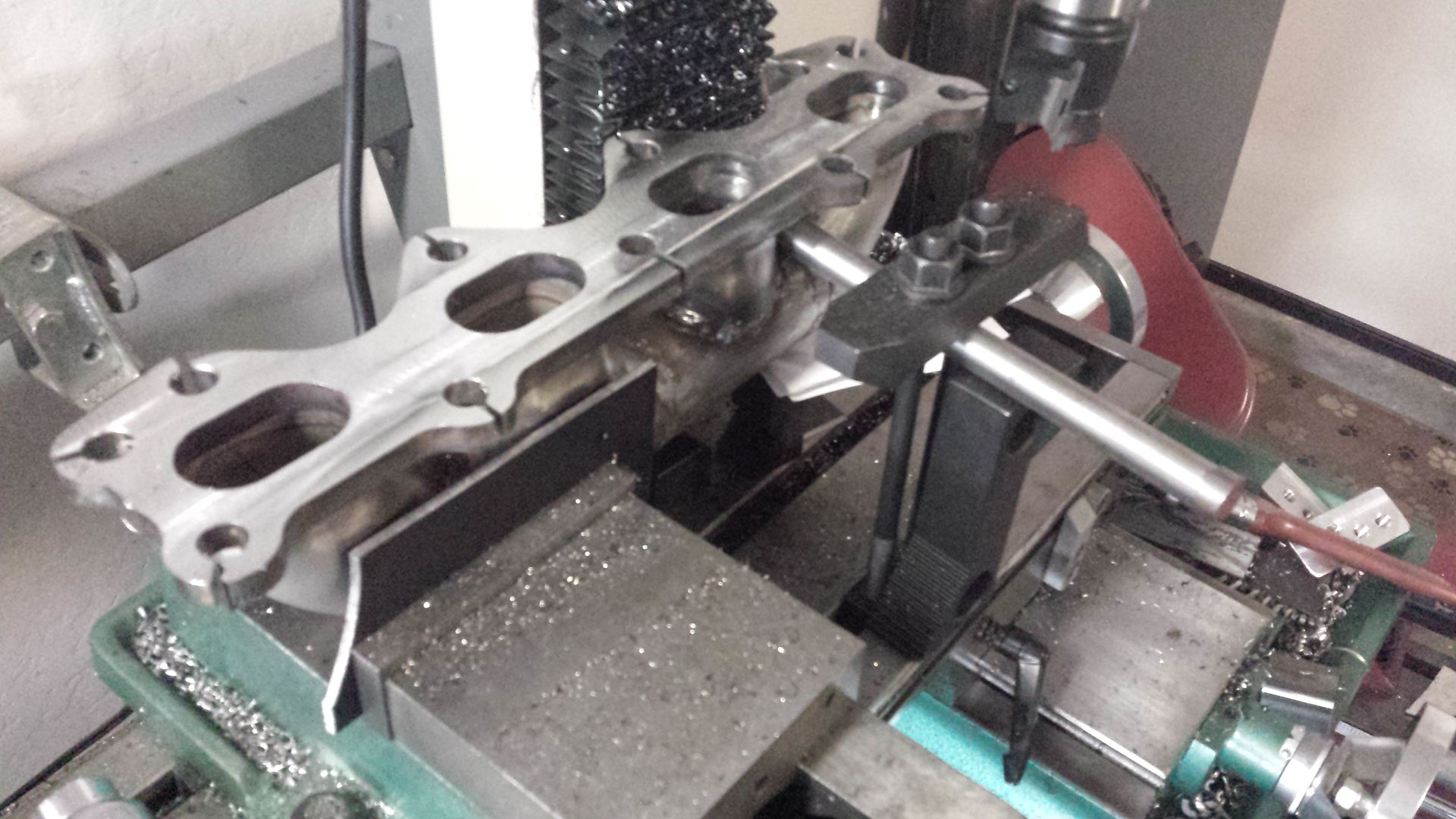
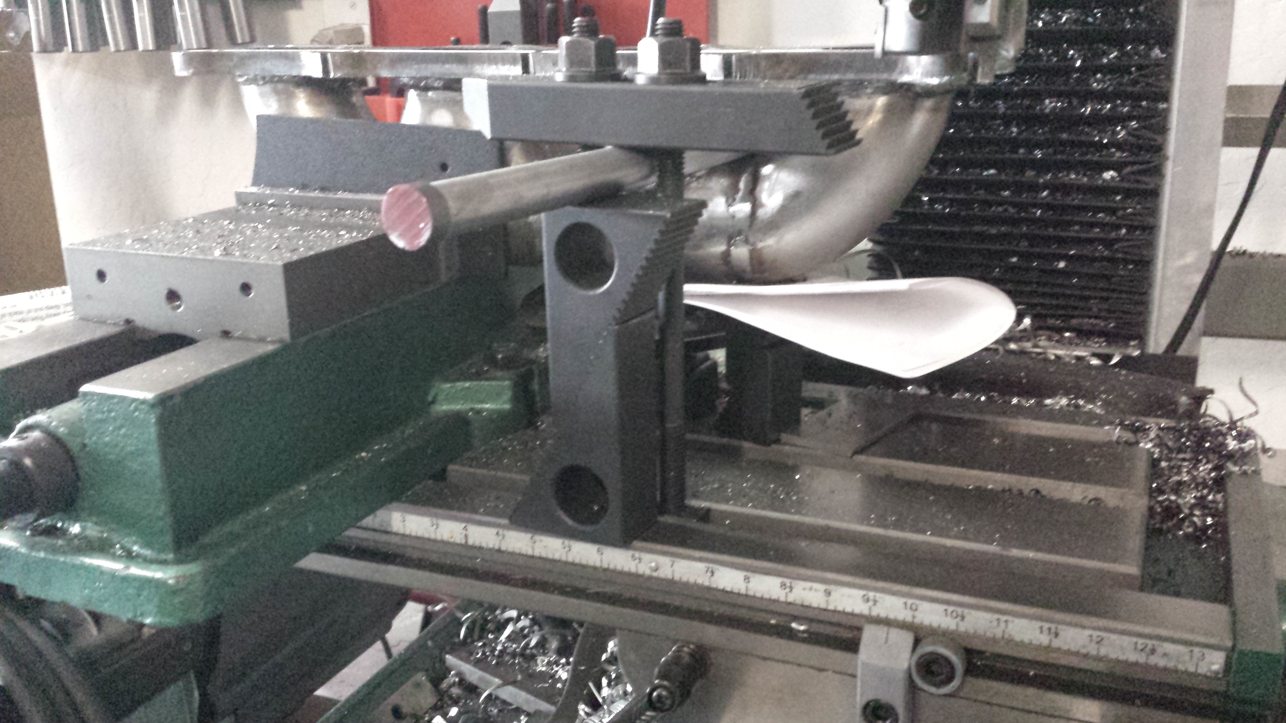
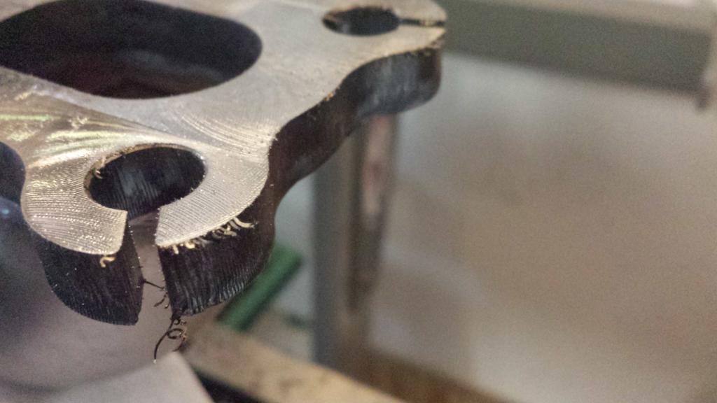
just need to do relief cuts and deburr
i milled the exhaust mani flat
i zeroed out between 2 and 3 and it took this cut. the area above the port is from filing.
+0.005
+0.0065 and that little corner of the bolt hole above the port is the only thing that is low with some mill scale sill left. done
so it was warped by roughly 0.0115"
and here is an artsy whatever closeup picture
and here is my ridiculous setup
just need to do relief cuts and deburr
Reply
0
0

Sean, I'm loving your fab skills!
Reply
0
0
Thread Starter
Joined: Sep 2012
Posts: 4,560
Total Cats: 1,143
From: your mom's house phoenix, AZ
Thanks ray.
You could use either 2O or P as they are both spare wires once you remove the afm. Its just a matter of which pins to jump at the afm. I used O for the iat sensor.
You could use either 2O or P as they are both spare wires once you remove the afm. Its just a matter of which pins to jump at the afm. I used O for the iat sensor.
Reply
0
0
ah, I see. Ours is just reversed one from another, and either way the st_sign fuse doesn't need to be pulled. I didn't know that before. I'm so lazy...need to read more.
Reply
0
0
Thread Starter
Joined: Sep 2012
Posts: 4,560
Total Cats: 1,143
From: your mom's house phoenix, AZ
so the internet rumor is that BMW pt no 11-62-1-427-586 is an inconel m10-1.50x40mm. they retail for around $30, but i find em as low as $15. i ordered 2 from one ebay seller and 1 from another. this is what they look like.
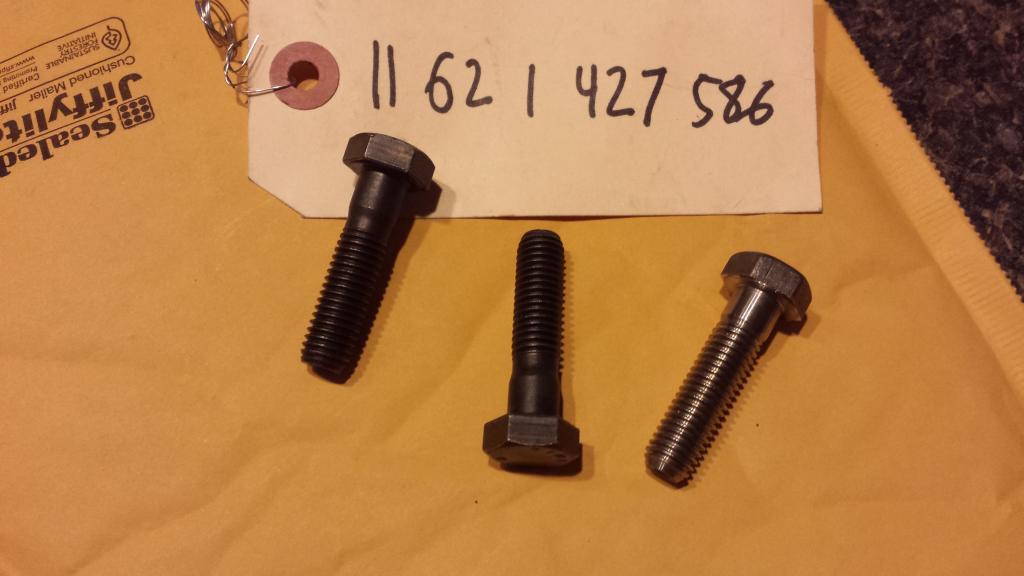

2 are black oxide and one looks to be raw, and was clearly machined on a lathe. you can even see where it was mounted on a live center. the threads were rolled on all 3 of them as far as i can tell by the surface finish.
they are certainly m10-1.50x40, the only question is are they really inconel? the machined one is consistent with what ive seen in the aftermarket for inconel hardware. the oxide one would be consistent with other known oem inconel fasteners like the nissans.
i read that inconel should spark test a very dull red with fine particles. i was thinking about trying it, but i dont do sparks tests and i dont know that i could distinguish it between anything else. i guess ill run em and see what happens when turbo gets installed.
are helicoils in the manifold side turbo flange a bad idea, anyone have track use with a helicoil?
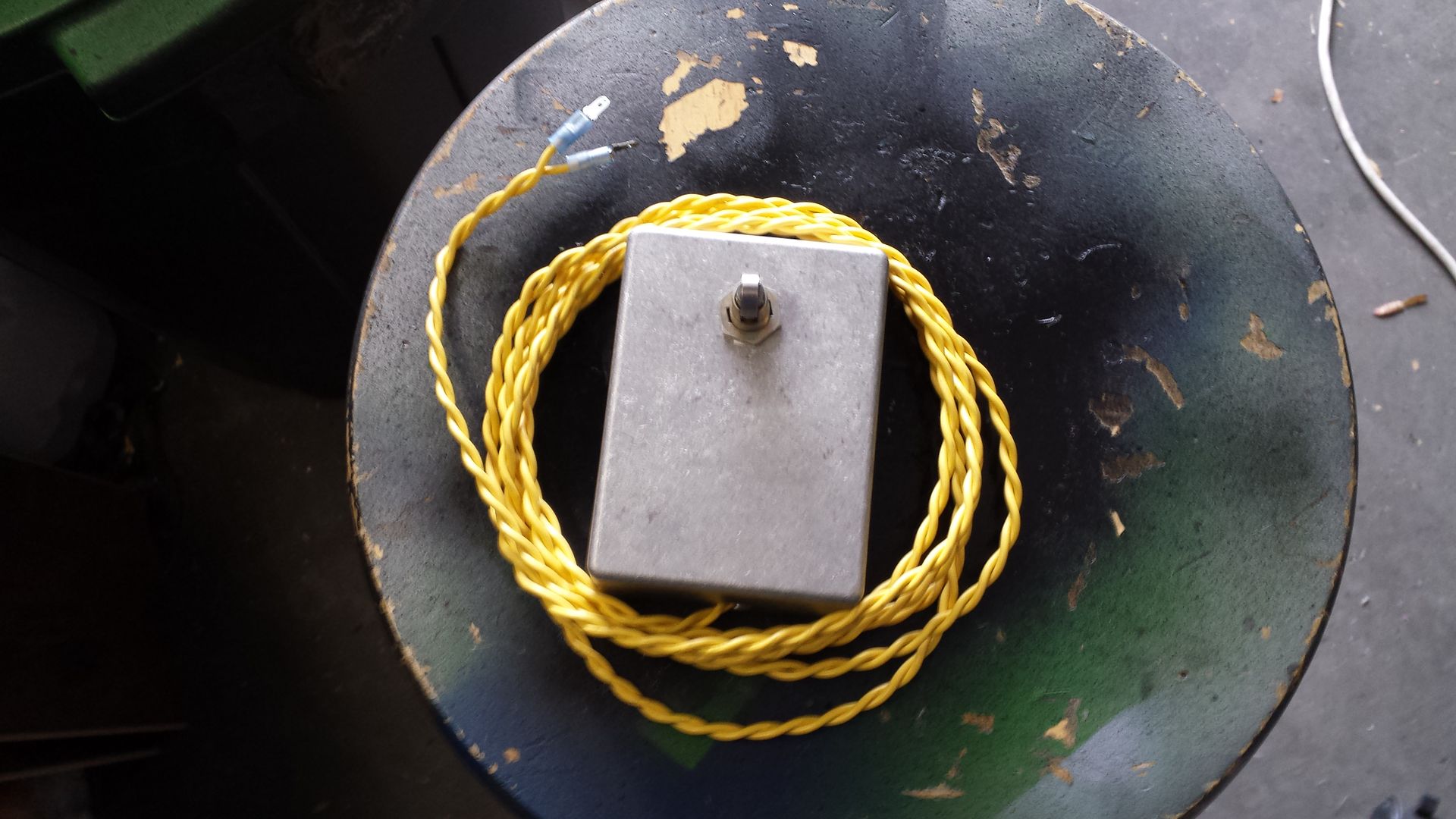
on a side note, i made a foot switch starter for cranking the engine from the front of the car when im alone.
Reply
0
0

Thread Starter
Joined: Sep 2012
Posts: 4,560
Total Cats: 1,143
From: your mom's house phoenix, AZ
will PM for address. thanks!
Reply
0
0
Thread Starter
Joined: Sep 2012
Posts: 4,560
Total Cats: 1,143
From: your mom's house phoenix, AZ
when i fubared one of my toyota cops, that's what was happening. basically the single coil was holding the signal to ground so I lost my tach.
It should pulse from 12v to ground when working properly. the 1K resistor you add is providing the pull-up to 12v that you remove when you pull out the stock ECU (b/w 2I) that normally connects to the y/b wire on the ignitor, which goes to the diagnostics box and dash tach.
with jusy key on, you should see 12v on that signal, then see it pulse to ground as teh coils fire. the signal is converted, based on the rate of 4 pulses, to move your tachometer.
so back to this.
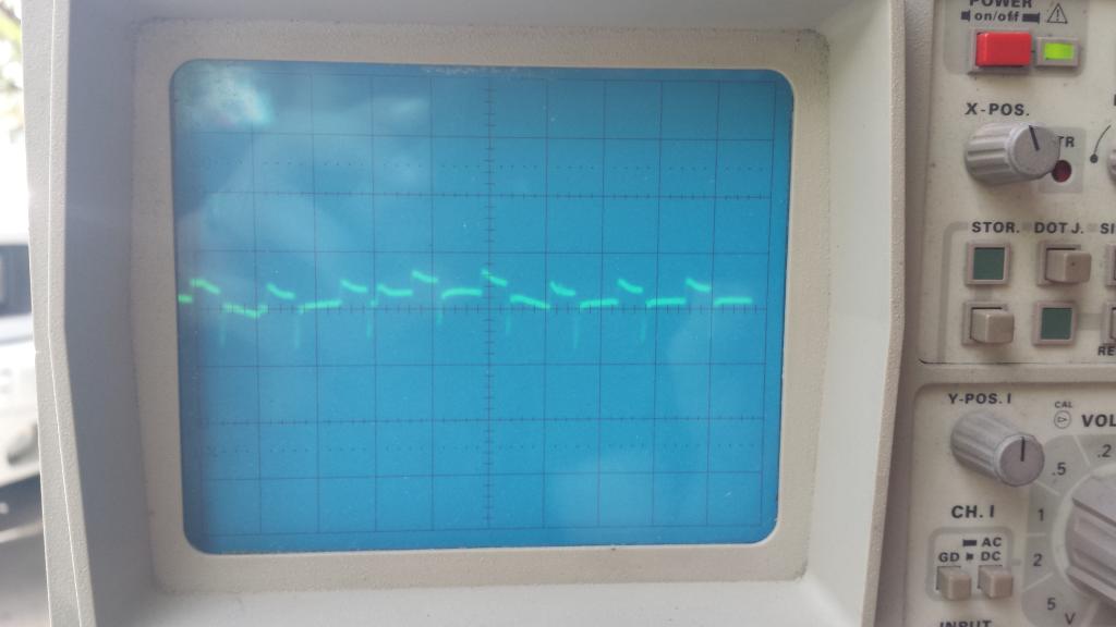
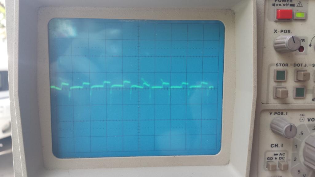
this is probing the yel/blu wire at the ignition connector, probe grounded to chassis
the wave looks like ****, and was fluctuating in waveform and what appeared to be a small fluctuating dc offset. no pulse width or frequency change with rpm.
about 0.9V P-P(and i mean from the very bottom of that nasty spike, not the actual square). i dont recall whether time was on 1 or 2 milliseconds/div, maybe it was microseconds lol. i dont see why it matters when it doesnt change with rpm.
these were all taken about 1/2 second apart


Reply
0
0
Thread Starter
Joined: Sep 2012
Posts: 4,560
Total Cats: 1,143
From: your mom's house phoenix, AZ
I was not aware of that. Im was curious if I could heli coil the manifold because I already drilled for m10 bolts, and if the bmws didn't work out, I was going to go with tse studs or maybe try the m8 nissan bolts. I don't see why heli coils wont work but everybody seems to have the opinion they won't.
I found a thread where one of the moderators mentions that he runs a heli coil with out issues in a cast mani.
I would prefer bolts for a number reasons and the Subaru flange allows for them. But if things don't work out, those would a good alternative. Is anyone using them on the track with success to verify?
Reply
0
0
No I dont know of any miata running them at the track. But they seem fine with the 15billion �F EGTs of the rotaries. Why would you ever choose bolts when studs are an option? Thats like choosing to buy a 1.6 when there's a 1.8 for sale right next to it for the same price.
Reply
0
0
Thread Starter
Joined: Sep 2012
Posts: 4,560
Total Cats: 1,143
From: your mom's house phoenix, AZ
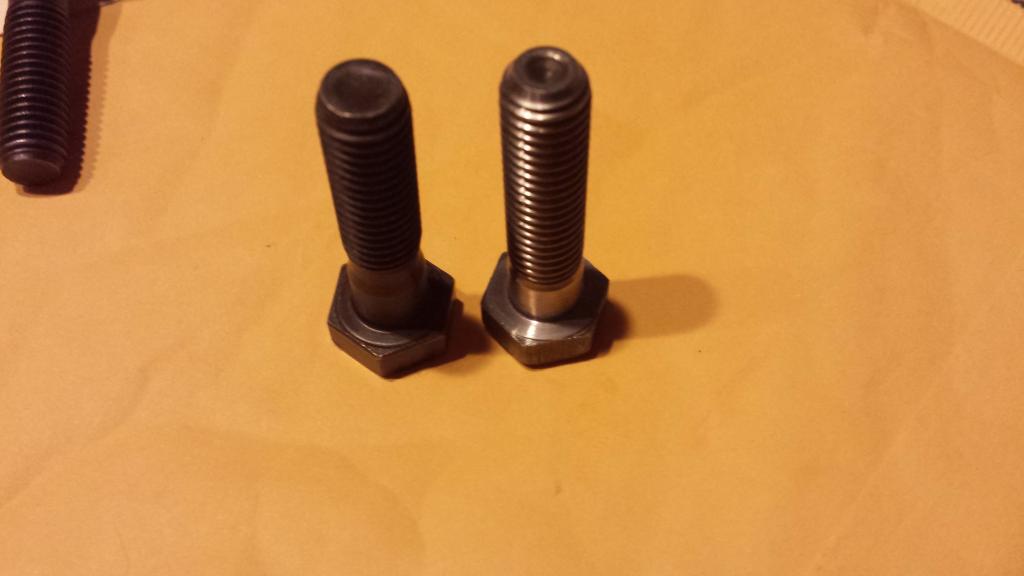
many thanks to Efini~FC3S for material testing these bolts, we now have conclusive evidence that the bimmer crowd is full of ****. BMW part number 11-62-1-427-586 is NOT inconel. its a SS. we believe it to be of the 422 variety. comparison to inco found here
Compare Materials: Inconel 718 (2.4668, N07718, NiCr19NbMo, NA51) vs. AISI 422 (S42200) Stainless Steel :: MakeItFrom.com
422 is of the high tempurature variety, but obviously not to the extent of inconel. they will more than likely make great downpipe bolts.
results:
Cr = 11%
V = 0.3%
Mn = 0.6%
Mo = 0.8%
Ni = 0.45%
Fe = ~86%
in other news, i got a new used ignitor from ebay. "guranteed" working, tested blah blah blah. also got some bits to finish the dash panel. a usb charger and volt meter setup, and a panel mount usb for the MS. ordered an ultrashield camlock with individual shoulders. so now i need to go pick up some steel and a co2 tank to make a harness bar. door bars may be the cards to but i still need to get started on my diy frog arms. its too hot outside lately to work on anything though. bleh.
Reply
0
0
Thread Starter
Joined: Sep 2012
Posts: 4,560
Total Cats: 1,143
From: your mom's house phoenix, AZ
ive been chipping away at it slowly
i still wasnt quite happy with the seat angle, it needed to recline more. i took it back out and shaved the rear mounts as thin as they could go and added a 6mm spacer to the front mounts. this gave me another 1.5 degrees. it made all the difference in the world, which surprised me for such a small change.
used ignitor from ebay=yay!
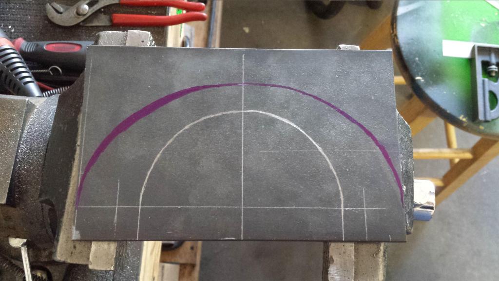
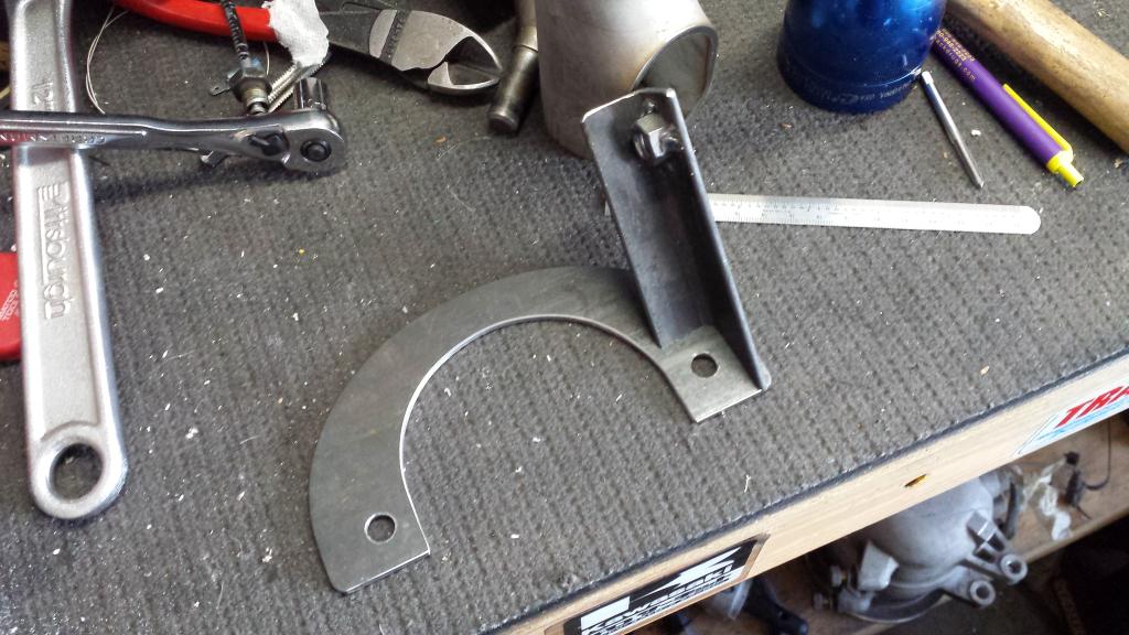
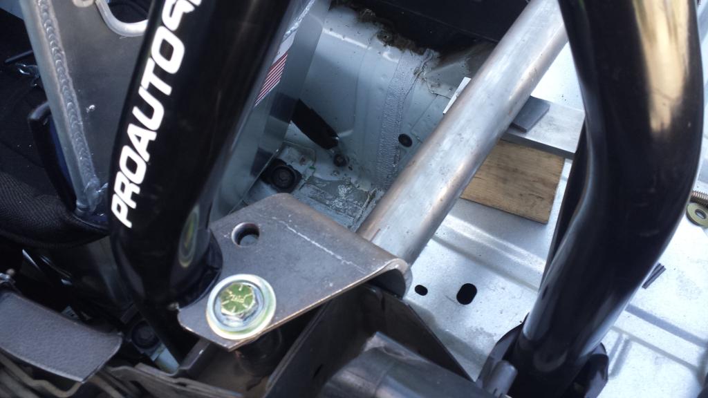
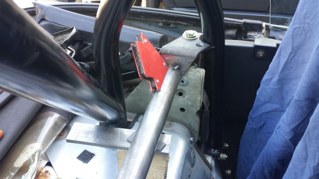
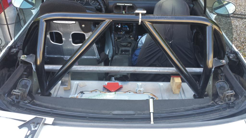
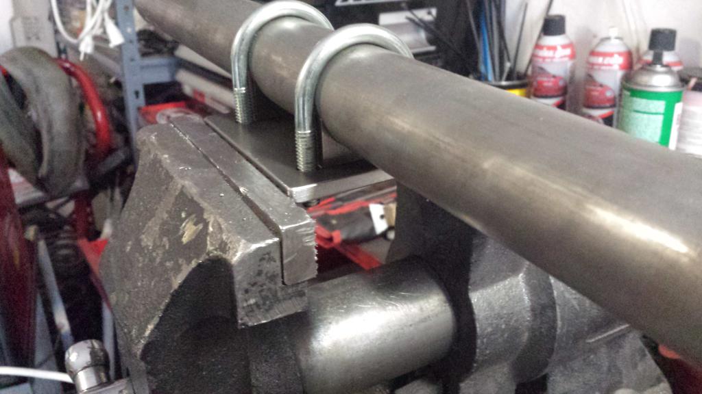
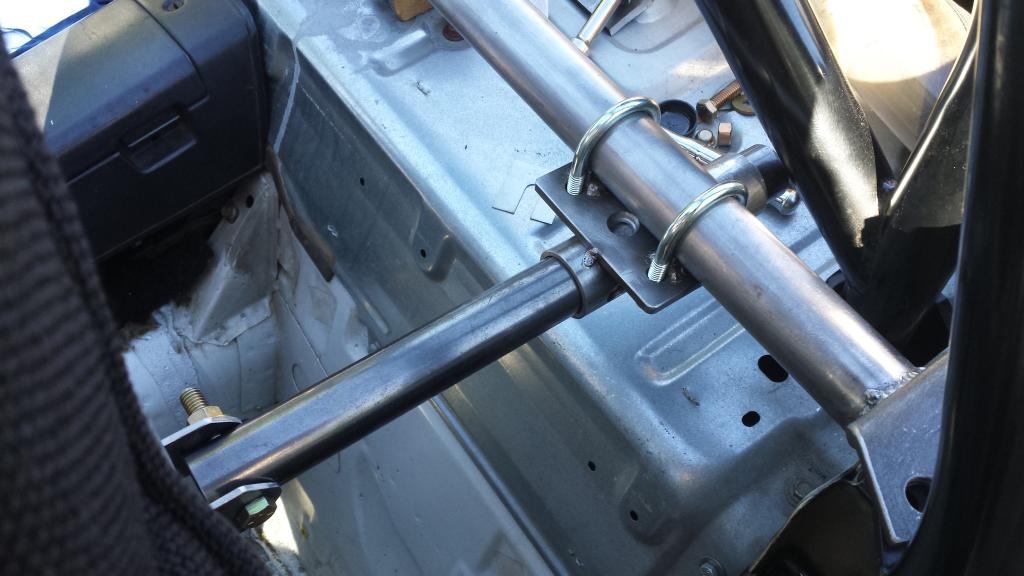
here is the evolution of a MC brace
harness bar
i started with this piece of cold rolled and made a template.

i bent it on an iron worker and this happens
no V-braking 1/4" cold rolled i guess. switched to hot rolled.
back brace
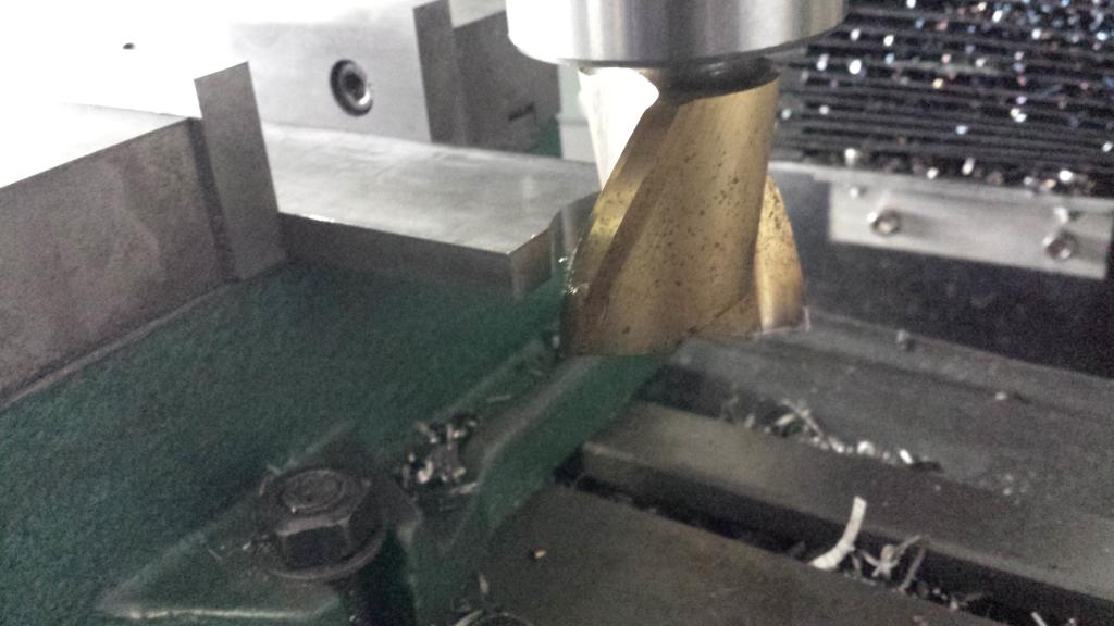
i milled the ends of a peice of 5/16x1.5" plate to half rounds with a 1.5" end mill.
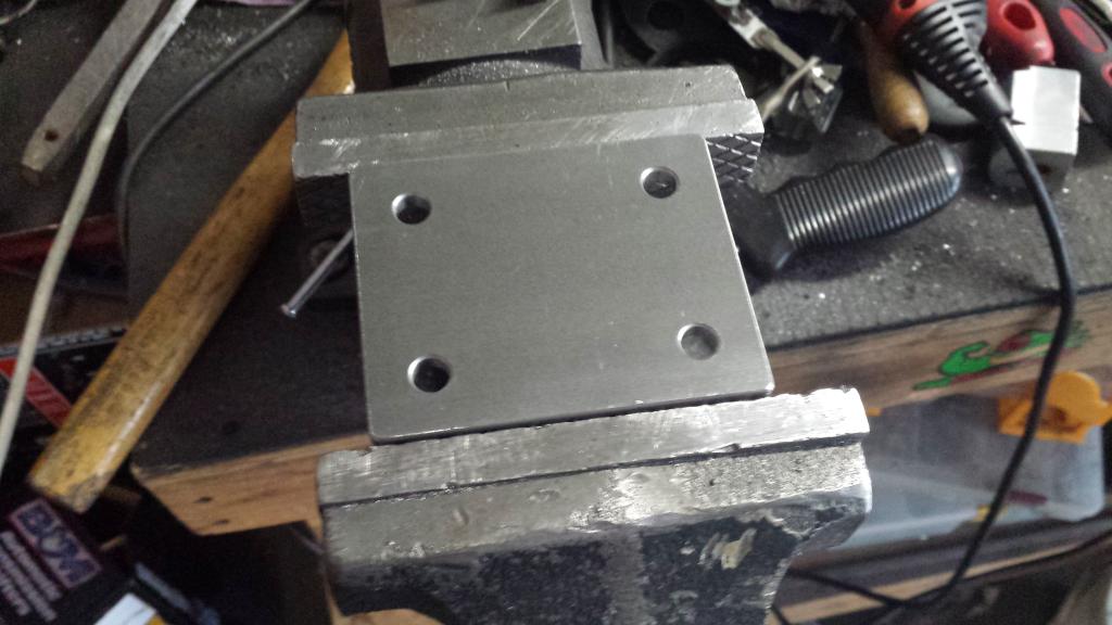
i installed holes into a plate

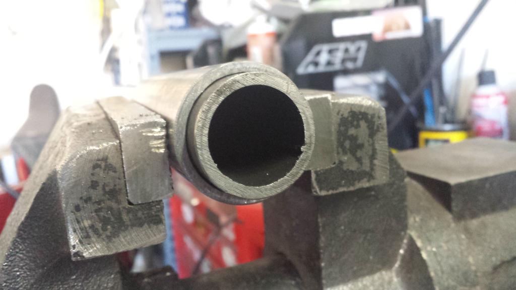
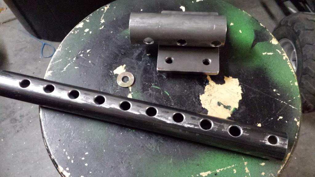
left over 1.5"x0.120" DOM from the harness bar and 1.25"x0.137" from a previous project
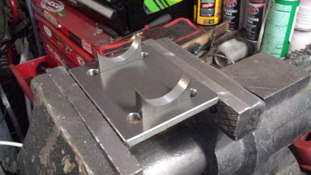
seat plate thingy
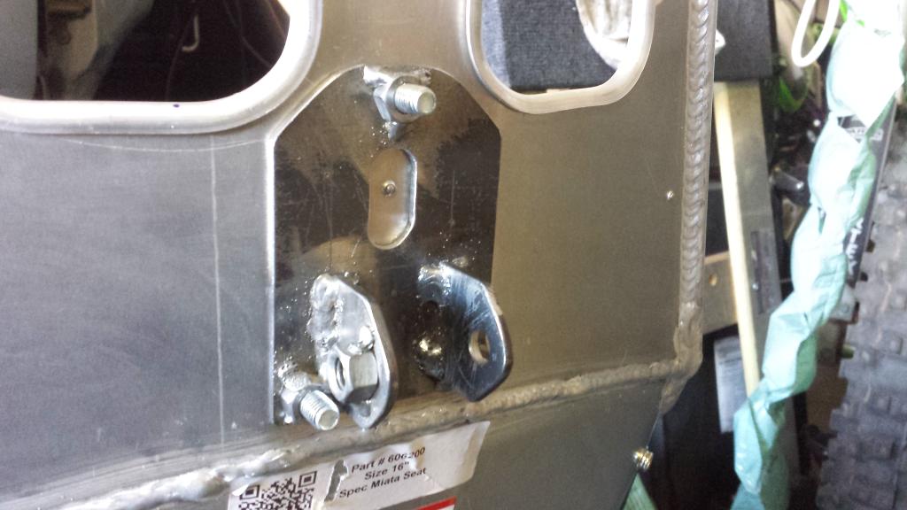
all mounted up, it really solidifies the seat
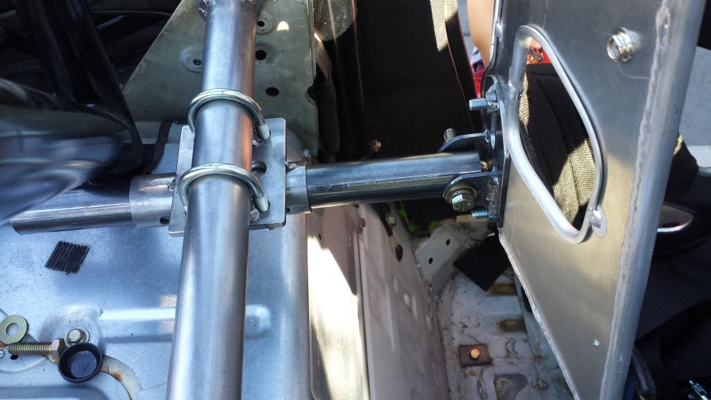
the seat sliders adjust in 10mm increments. im going to turn a 7/16" pin on the lathe and obviously couldnt drill holes every 10mm. so i drilled them 30mm apart on the inner bar, and 3, 40mm apart on the outer bar. i can now use every increment on the sliders because math.
i just need to finish weld and paint everything
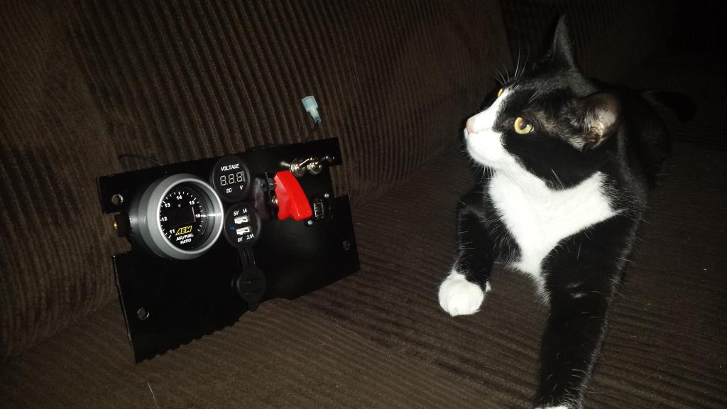
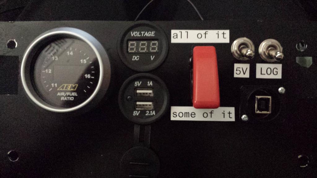
i added a usb charger, volt meter, panel mount usb for the megasquirt, and some various switches to the gauge panel.
and i put some labels on crooked.
i still wasnt quite happy with the seat angle, it needed to recline more. i took it back out and shaved the rear mounts as thin as they could go and added a 6mm spacer to the front mounts. this gave me another 1.5 degrees. it made all the difference in the world, which surprised me for such a small change.
used ignitor from ebay=yay!
here is the evolution of a MC brace
harness bar
i started with this piece of cold rolled and made a template.
i bent it on an iron worker and this happens
no V-braking 1/4" cold rolled i guess. switched to hot rolled.
back brace
i milled the ends of a peice of 5/16x1.5" plate to half rounds with a 1.5" end mill.
i installed holes into a plate
left over 1.5"x0.120" DOM from the harness bar and 1.25"x0.137" from a previous project
seat plate thingy
all mounted up, it really solidifies the seat
the seat sliders adjust in 10mm increments. im going to turn a 7/16" pin on the lathe and obviously couldnt drill holes every 10mm. so i drilled them 30mm apart on the inner bar, and 3, 40mm apart on the outer bar. i can now use every increment on the sliders because math.
i just need to finish weld and paint everything
i added a usb charger, volt meter, panel mount usb for the megasquirt, and some various switches to the gauge panel.
and i put some labels on crooked.
Last edited by hi_im_sean; Oct 2, 2014 at 11:36 PM.
Reply
5
5


