
Alternator Control. Dead nailed. MS3 / MS3-Pro / MSPNP-Pro


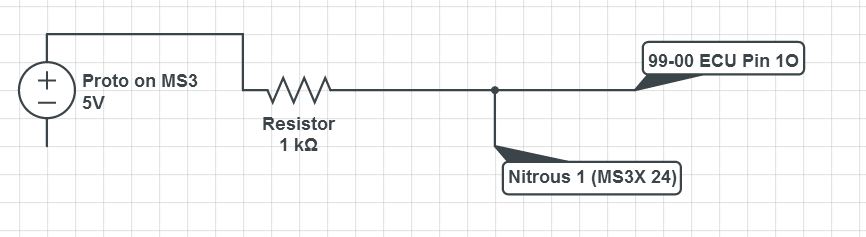
I took the 5V for the pullup from one of the bias resistor locations on the MS3X board and soldered a resistor on the bottom of the MS3X board. Seems to work just fine.
Reply
 0
0

0


Thread Starter

Joined: Jul 2006
Posts: 12,659
Total Cats: 134
From: atlanta-ish
Because that's how Mazda did it, and I haven't tested with a 12V pullup.

Reply
0
0

This is not working, anyone care to tell me what I'm doing wrong?
Last edited by Schuyler; Jun 21, 2014 at 11:12 PM. Reason: Not on phone now, replaced pictures with screenshots
Reply
0
0

Senior Member
Joined: Nov 2007
Posts: 999
Total Cats: 73
From: Belgium
Not working for me either (although I'm using JS0). Just like the first iteration of the software control, I'm charging near 20V, didn't blow up anything this time.
Reverting back to hardware control.
Reverting back to hardware control.
Reply
0
0

Senior Member
Joined: Nov 2007
Posts: 999
Total Cats: 73
From: Belgium
Edit: gave it another try and tested with JS10 and that didn't work either. Then tried D15 to find out it's used by the knock sensor. Then I gave up. I used a 1K pullup to 5V each try.
Last edited by WestfieldMX5; Jun 22, 2014 at 03:57 PM.
Reply
0
0

Those are plentiful, any Mazda from about 94 to 98 usually have the same type (fitting, offset, connector, multirib, internal IC). At least the 323's and 626's I have raided.
A cheepo LED panel Voltmeter helps keep this **** in check.
A cheepo LED panel Voltmeter helps keep this **** in check.
Reply
0
0

Lack of docs is by far the worst thing about MS. There should be at least some documentation before any new feature is made available to the public.
Case in point, there's **** all on the LTFT feature, still.
Reply
0
0
Why did I leave the board I bought from you at my house at school Frank? Why'd you let me do it? Was hoping I could get things working with this feature to save myself the trip to go get it. But since a lack of a functioning alternator system is the only thing keeping me from tuning, i'm getting annoyed to the point I might have to do just that, or have a roommate ship it. Car is idling great when hooked to a charger to keep the battery going.
Reply
0
0
Thread Starter
Joined: Jul 2006
Posts: 12,659
Total Cats: 134
From: atlanta-ish
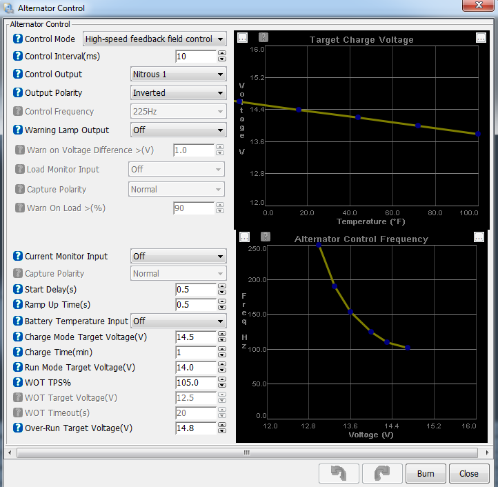
Looks fine -- try non-inverted output.
Reply
0
0
I'll give that a shot tomorrow evening and report back. Car is a 99-00.
EDIT: I've seen it referenced more than once that nitrous 1/2 can only be used in certain applications. Would this be on of those applications it CANNOT be used?
EDIT: I've seen it referenced more than once that nitrous 1/2 can only be used in certain applications. Would this be on of those applications it CANNOT be used?
Last edited by Schuyler; Jun 22, 2014 at 10:57 PM.
Reply
0
0


Reply
0
0
Senior Member
Joined: Nov 2007
Posts: 999
Total Cats: 73
From: Belgium

Lost pretty much the entire afternoon on it yesterday . Not saying software control doesn't work, just that *I* couldn't get it running, just like the first iteration.
Figured I might as well install my board. 5 mins later, my battery voltage is rock solid to 0.1V precise and I can turn of the alternator at startup as well.
<Shrug and move on>
Reply
0
0
Thread Starter
Joined: Jul 2006
Posts: 12,659
Total Cats: 134
From: atlanta-ish
And the reason I've stopped building them. It's too time consuming trying to find all relevant information in several forums. And even then it's a nightmare.
Edit: gave it another try and tested with JS10 and that didn't work either. Then tried D15 to find out it's used by the knock sensor. Then I gave up. I used a 1K pullup to 5V each try.
Edit: gave it another try and tested with JS10 and that didn't work either. Then tried D15 to find out it's used by the knock sensor. Then I gave up. I used a 1K pullup to 5V each try.
If you wired JS10 to Alt field with a 5V pullup, you're going to have a bad day. That should command the alternator at 100% duty cycle. JS10 might work for field control without a pullup, but I wouldn't try because I don't know how much current the field will sync.
If you add a pullup to JS0, you're going to have a bad day. JS0 switches between 12V and ground. It's a stepper output.
To use either of these pins, you should add additional hardware.
Why not use a spare PWM output with pullup as shown in my posts?
Reply
0
0


