

3d printed intake for N/A NA miatas


Thread Starter

Joined: Jul 2012
Posts: 792
Total Cats: 143
From: durham NC
The youtube version is blocked in the US but I found it on daily motion:
http://www.dailymotion.com/video/x3rdsi7
That is the first time I have seen someone do bladder molding with wet layup, which is my plan. They are doing resin infusion which I am not planning on. It is interesting that they aren't using any flow media, breather material, or release material.
http://www.dailymotion.com/video/x3rdsi7
That is the first time I have seen someone do bladder molding with wet layup, which is my plan. They are doing resin infusion which I am not planning on. It is interesting that they aren't using any flow media, breather material, or release material.
Reply
 0
0

0
Thread Starter
Joined: Jul 2012
Posts: 792
Total Cats: 143
From: durham NC
Not for most people. Some early chassis don't have a hole in the radiator support. I haven't been able to figure out exactly which cars since it isn't something obvious like all 1990 cars.
Reply
0
0

Awesome results. I guess the clean sheet design was worth it. A naturally aspirated miata engine is never going to flow close to 350 CFM. An online calculator says a engine with 2000cc displacement at 8500rpm and VE of 110 would be consuming 240 cfm.
Yeah, I probably need a name for it. I was thinking just Durham Composite intake.
Also, everyone should be giving cyotani props for doing CFD for me.
Yeah, I probably need a name for it. I was thinking just Durham Composite intake.
Also, everyone should be giving cyotani props for doing CFD for me.
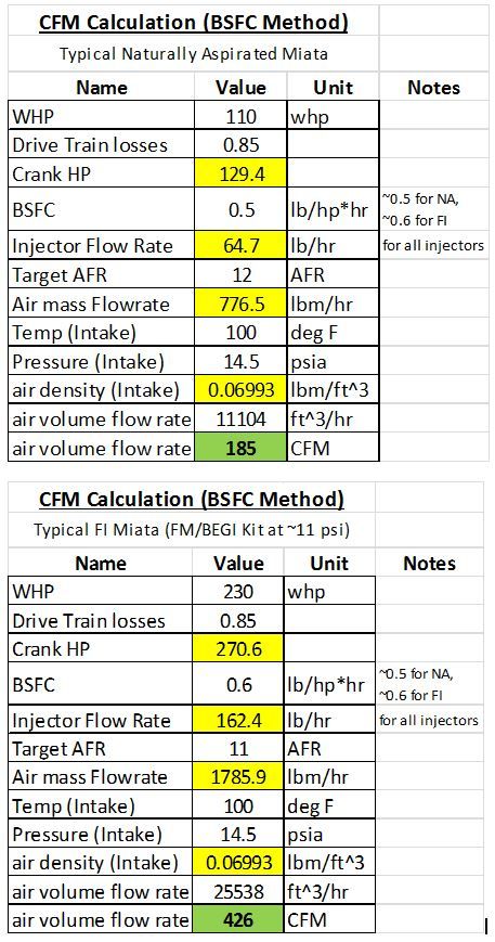
Also, I'd use the BSFC method rather than that method. Solve for required Air to support a certain WHP assuming a specific BSFC. It would be good to get a stock CFM and a typical 230 whp turbo build CFM and solve for the pressure drop in both those cases.
Reply
0
0

Junior Member
Joined: May 2010
Posts: 135
Total Cats: -52
From: Tampa, Florida
Reply
0
0
Reply
0
0

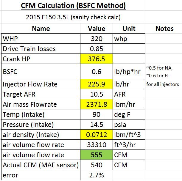
Here is a quick sanity check on the spreadsheet. This is a 3.5L EcoBoost I've had on the DYNO often for work over the past few months. We instrumented it with our own MAF sensor calibrated on a flow bench.
at 320 WHP it flowed 540 CFM.
AFR was 10.5.
Spreadsheet seems to check out okay.
at 320 WHP it flowed 540 CFM.
AFR was 10.5.
Spreadsheet seems to check out okay.
Reply
0
0
Thread Starter
Joined: Jul 2012
Posts: 792
Total Cats: 143
From: durham NC
The target user base for this has been people making 140-160whp with NB engines that are close to stock internally. Knowing it causes minimal restriction at 350 cfm it seems also seems appropriate on a cost no object build making 190whp. Also, this latest design might even fit on a k-swap car.
Reply
0
0
Reply
0
0

Thread Starter
Joined: Jul 2012
Posts: 792
Total Cats: 143
From: durham NC
I looked up the parts, they are way bigger than I was thinking. For this application, would that thickness be necessary? I think the stock crossover tube in the miata is about 2mm and is very strong.
Reply
0
0
Depends on the manufacturing process. These tubes are rotomolded (constant thickness process so we have no control of beefing up critical areas and thining out less stressed areas). Also blow molded tube are typically thinner so the material can fill the crevices of the mold easier. We could go thinner on the rotomolded tubes but the thickness and weight also adds a sense of quality in the part when you hold it. It feels more expensive than some of the thinner blow molded or plastic injected tubes.
Reply
0
0

Well, since I don't have a hood latch I want to install the 3d intake into that opending in hopes of achieving a total lenght of 22". I found out a 60 degree of the tb and another 45 to the intake will work perfectly. Some cutting of the hood needs to be done too. (Where the original latch was) I'll post pictures once it's done
Reply
0
0
Thread Starter
Joined: Jul 2012
Posts: 792
Total Cats: 143
From: durham NC
A few updates. First, the new design fits on my car. I hammered my hood about a year ago so I need to test fit it on a stock hood before having aluminum molds machined but it looks like the 2016 revision is going to work.
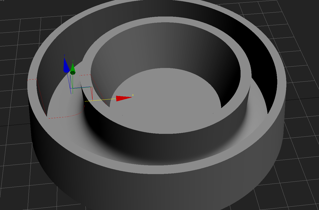
Second, the selection of air filters that fit in the bumper area is really poor. I really like the AEM dryflow filters for several reasons, one of them being the bell mouth they integrate into the flange. AEM doesn't make any filters that are narrow enough to fit. I contacted them about a run of custom size filters and they referred me to K&N. My solution- I found a green filter that is only slightly over sized and uses a 3.5" flange opening. I designed a simple mold to pour silicone rubber into to make a bell mouthed flange reducer with an offset hole. The upside is being able to fit a significantly larger air filter + getting that bell mouth geometry.
Second, the selection of air filters that fit in the bumper area is really poor. I really like the AEM dryflow filters for several reasons, one of them being the bell mouth they integrate into the flange. AEM doesn't make any filters that are narrow enough to fit. I contacted them about a run of custom size filters and they referred me to K&N. My solution- I found a green filter that is only slightly over sized and uses a 3.5" flange opening. I designed a simple mold to pour silicone rubber into to make a bell mouthed flange reducer with an offset hole. The upside is being able to fit a significantly larger air filter + getting that bell mouth geometry.
Reply
0
0


