

Eric Anderson's Supercharged SSM Miata

Thread Starter
Joined: Jan 2011
Posts: 1,234
Total Cats: 283
From: Chattanooga, Tn
Yes, the block was final honed with all the fasteners torqued to represent static load on the block. I do however find it odd that we obsess over having a motor that is perfect in a static state(on the engine stand) when it really needs to be perfect when it's in a dynamic state(running under load).
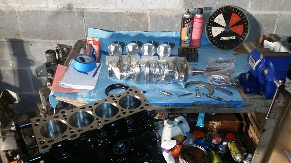
Here are a few pics of the progress so far.
Short block parts after final cleaning before first round of measurements and test fittings.
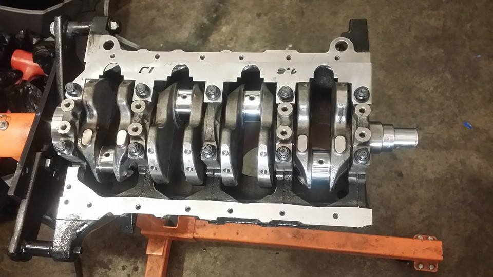
Got the main clearances set, the crank scrapper fitted and the crank final installed in the block.
 [/URL]
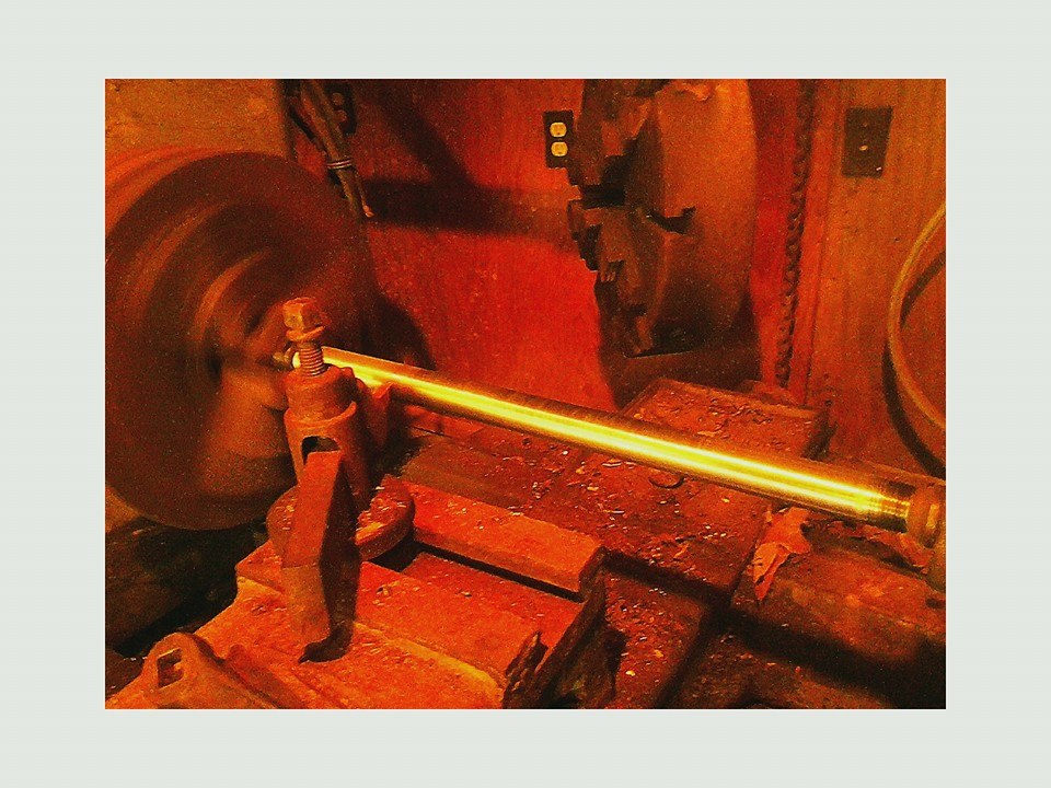
Next comes the part I am most anxious about. With the new cams being as aggressive as they are, the over-sized valves and the high compression pistons, I am assuming I will have an interference motor. While "claying" a motor will tell you if you have clearance, it will not tell you WHEN you have that clearance and even then it will only get you "hand grenade close." So I went to the store, bought some bar stock, threw it in the lathe and built a fixture with which I will be able to measure the piston to valve clearance more accurately using a dial gauge. I'm going to wait until I am able to determine if any material needs to be removed from the pistons before I final install them in the block.
More to come.
Here are a few pics of the progress so far.
Short block parts after final cleaning before first round of measurements and test fittings.
Got the main clearances set, the crank scrapper fitted and the crank final installed in the block.
[/URL]Next comes the part I am most anxious about. With the new cams being as aggressive as they are, the over-sized valves and the high compression pistons, I am assuming I will have an interference motor. While "claying" a motor will tell you if you have clearance, it will not tell you WHEN you have that clearance and even then it will only get you "hand grenade close." So I went to the store, bought some bar stock, threw it in the lathe and built a fixture with which I will be able to measure the piston to valve clearance more accurately using a dial gauge. I'm going to wait until I am able to determine if any material needs to be removed from the pistons before I final install them in the block.
More to come.
Last edited by TNTUBA; Jan 7, 2015 at 08:04 AM.
Reply
 0
0

0

Yes, the block was final honed with all the fasteners torqued to represent static load on the block. I do however find it odd that we obsess over having a motor that is perfect in a static state(on the engine stand) when it really needs to be perfect when it's in a dynamic state(vibrating under load)

Measuring clerance is not an easy task (more than one possibilty for brain farts), especially if the cut-outs are tight. Will the valve fit? Sure, but will it hit the edge, since the piston is moving towards an already semi-open intake valve...
Are you planning to use a "feeler" valve and assume the other 7 will have the same clearance?
A table with distance per crank angle I assume and clearance from subtracting the lift table? This makes it possible to know something about clearance when phasing the cams.
I did not do my own thankfully, and "we" found clearance all the way to 34 degrees advance on the intake side (VVT only adds a number of more measurement cycles...). But my cams are different, to say the least.
Reply
0
0
Thread Starter
Joined: Jan 2011
Posts: 1,234
Total Cats: 283
From: Chattanooga, Tn
Driving...I'll give more detail later. The way you measure side clearance of the valve is to take a valve, cut the head off the valve, sharpen the stem to a point. Stick that into the valve guide and tap the end of it just enough to make an indentation in the valve relief. That gives you the exact center of where each valve will sit in relation to the valve relief. You then take a set of calipers and measure the exact diameter of the valve, you then set a machinest's compass as the radius. You the place the point in the dimple on the piston and can measure the side clearance with a feeler gauge. Much more accurate than clay alone. If you are only using clay....you are doing it wrong.
Reply
0
0
I was thinking about the dynamics of a relief moving upwards and a valve moving down at an angle. The closest distance can be the edge of the relief some angle before TDC.
But such theorized issues can be solved by chamfering the reliefs...
But such theorized issues can be solved by chamfering the reliefs...
Reply
0
0

Junior Member
Joined: Dec 2006
Posts: 191
Total Cats: 8
Driving...I'll give more detail later. The way you measure side clearance of the valve is to take a valve, cut the head off the valve, sharpen the stem to a point. Stick that into the valve guide and tap the end of it just enough to make an indentation in the valve relief. That gives you the exact center of where each valve will sit in relation to the valve relief. You then take a set of calipers and measure the exact diameter of the valve, you then set a machinest's compass as the radius. You the place the point in the dimple on the piston and can measure the side clearance with a feeler gauge. Much more accurate than clay alone. If you are only using clay....you are doing it wrong.
I do agree though, clay, while useful is only a rough guide at best. For piston to head clearance in the kart I use solder instead with a touch of lithium grease to keep it in place(parallel to the piston pin.)
I'm also interested in an elaboration of your valve piston method with the "cam blank"? Normally I put in a lightweight spring(1-2lbs, found at Lowe's racing supply), then setup a dial gauge to be in line with the lifter(but next to the cam). then you just have to push on the lifter to get a reading. It does mean a second disassembly/reassembly of the head though.
Nik,
In the engines I've worked with, the minimum valve clearance is never at TDC, but sometime when the valve chasing, or being chased by the piston depending on if you're talking intake or exhaust valves.
Reply
0
0
Thread Starter
Joined: Jan 2011
Posts: 1,234
Total Cats: 283
From: Chattanooga, Tn
Sorry for the delay. The valve reliefs in the pistons are cut at an angle that mirrors the valve angle in the head.
So you don't find the center of the valve at the valve angle, then use the compass at the angle of the deck surface.
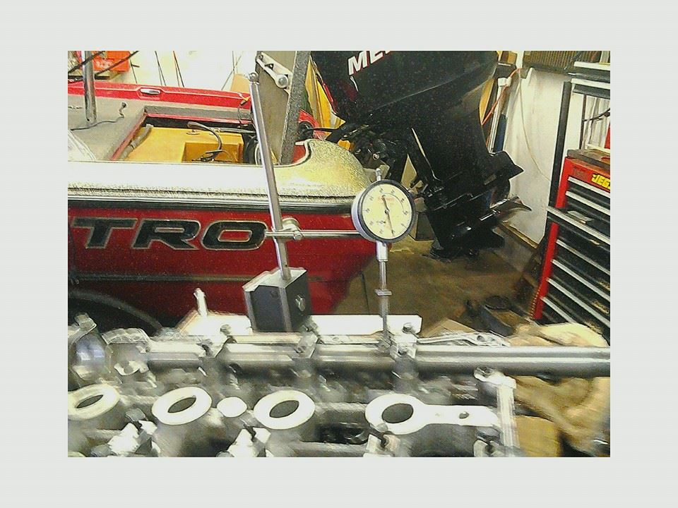
I would be interested to see how you were able to set up the dial indicator to be perpendicular to the tip of the valve, articulate the valve with the cam installed and have the dial indicator stay in contact with the lifter once the top of the lifter has recessed into the lifter bore. I couldn't figure out how to make that work...and I'm pretty smart
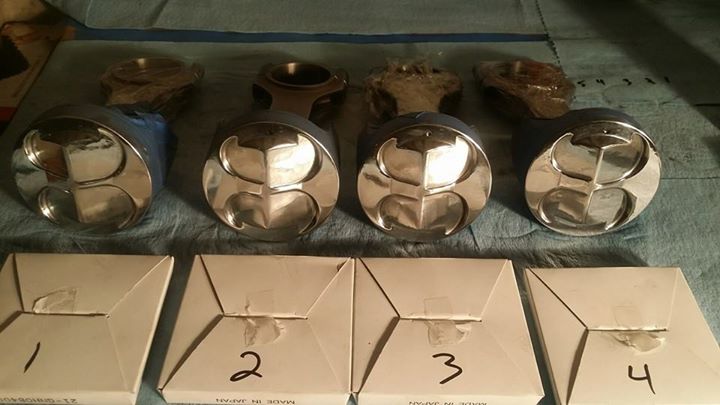
On to a few updates, I finished cleaning the pistons and have set the ring end gaps. I should have the head back from the machine shop today, so I will be able to start my actual Piston to Valve clearance checks and if everything checks out I should have the motor ready to install this weekend. I have waited to install the rods and pistons in the off chance that I need to mill some material off the pistons to accommodate the new valves and the new lift.
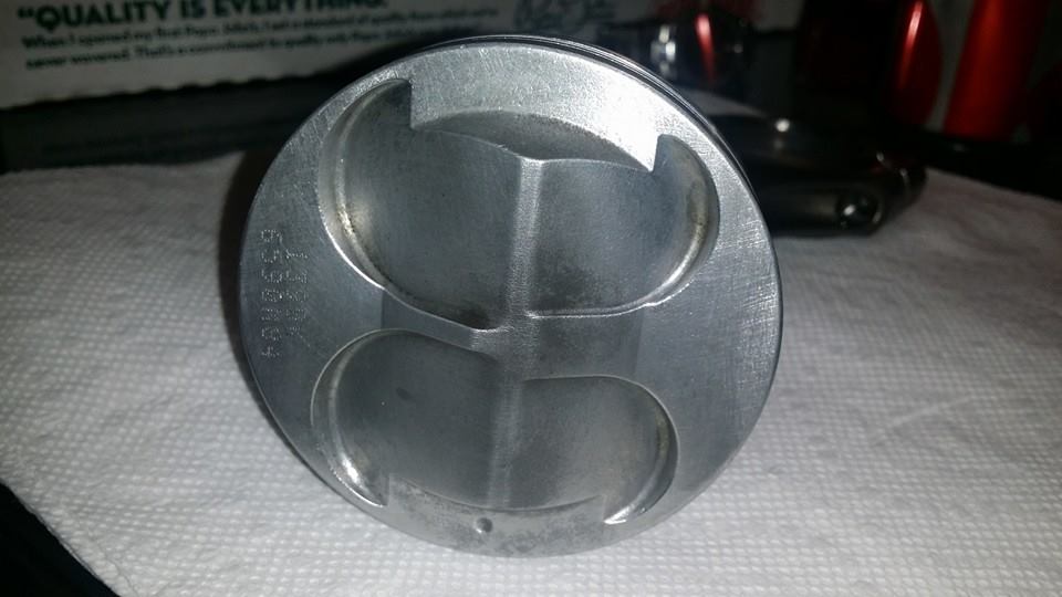
There are a ton of schools of thought on piston coatings and piston finishes. One of the more credible (to me) sources did some actual testing on piston finishes and the difference were significant enough to not be confused with "white noise" on the engine dyno. This test used the following piston finishes. Factory machined, coated, Satin, Polished and then each of those pistons again coated with a layer of carbon. The polished piston actually made the most power when clean and when covered with a layer of carbon. The difference wasn't huge but it was meaningful. He then tested the pistons for heat rejection and found that the Polished piston was able to reject more heat back into the combustion chamber than the other pistons as well. So, I spent about 30-40 min with a dremmel tool and now all my slugs look like this. It should be important to note that this tester does not sell piston polishing service, pistons or piston coatings. Just a machine shop / tuning shop that has been building huge horsepower numbers for several decades.
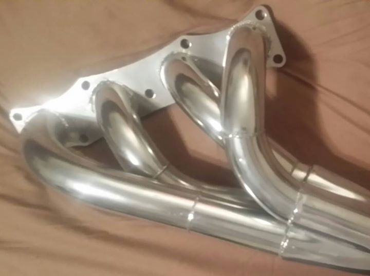
And finally, The header I built last year was an experiment. I didn't spend the money to build it out of stainless because I wasn't sure if it would actually work the way the math said it would. Well it worked. So I was toying with the idea of rebuilding it out of stainless when someone suggested having it coated instead. So I spoke with the guys at Nitroplate up in Nashville, Tn and they were great to deal with. Got the header back yesterday and I'm really impressed with how it turned out. The cleaned and coated both the inside and outside of the header and including shipping the total bill was less than $180.00. Read a online review of their coating that showed on a engine dyno the surface heat delta for this coating to be over 500 degrees lower than the same header non coated. If the delta is half that, it was worth it to me.
That's all I've got for now. Will report back when I have more time and have made more progress.
So you don't find the center of the valve at the valve angle, then use the compass at the angle of the deck surface.
I would be interested to see how you were able to set up the dial indicator to be perpendicular to the tip of the valve, articulate the valve with the cam installed and have the dial indicator stay in contact with the lifter once the top of the lifter has recessed into the lifter bore. I couldn't figure out how to make that work...and I'm pretty smart
On to a few updates, I finished cleaning the pistons and have set the ring end gaps. I should have the head back from the machine shop today, so I will be able to start my actual Piston to Valve clearance checks and if everything checks out I should have the motor ready to install this weekend. I have waited to install the rods and pistons in the off chance that I need to mill some material off the pistons to accommodate the new valves and the new lift.
There are a ton of schools of thought on piston coatings and piston finishes. One of the more credible (to me) sources did some actual testing on piston finishes and the difference were significant enough to not be confused with "white noise" on the engine dyno. This test used the following piston finishes. Factory machined, coated, Satin, Polished and then each of those pistons again coated with a layer of carbon. The polished piston actually made the most power when clean and when covered with a layer of carbon. The difference wasn't huge but it was meaningful. He then tested the pistons for heat rejection and found that the Polished piston was able to reject more heat back into the combustion chamber than the other pistons as well. So, I spent about 30-40 min with a dremmel tool and now all my slugs look like this. It should be important to note that this tester does not sell piston polishing service, pistons or piston coatings. Just a machine shop / tuning shop that has been building huge horsepower numbers for several decades.
And finally, The header I built last year was an experiment. I didn't spend the money to build it out of stainless because I wasn't sure if it would actually work the way the math said it would. Well it worked. So I was toying with the idea of rebuilding it out of stainless when someone suggested having it coated instead. So I spoke with the guys at Nitroplate up in Nashville, Tn and they were great to deal with. Got the header back yesterday and I'm really impressed with how it turned out. The cleaned and coated both the inside and outside of the header and including shipping the total bill was less than $180.00. Read a online review of their coating that showed on a engine dyno the surface heat delta for this coating to be over 500 degrees lower than the same header non coated. If the delta is half that, it was worth it to me.
That's all I've got for now. Will report back when I have more time and have made more progress.
Reply
1
1

Junior Member
Joined: Dec 2013
Posts: 55
Total Cats: 9

Awesome updates. Thanks for sharing!
Reply
1
1
Thread Starter
Joined: Jan 2011
Posts: 1,234
Total Cats: 283
From: Chattanooga, Tn
No problem. I'm looking forward to seeing how it runs. And you are one of the guys I'd love to have drive the car sometime and give me your opinion on the setup. Hope to catch up with you at a tour and let you run it on the practice course.
Reply
0
0

Thread Starter
Joined: Jan 2011
Posts: 1,234
Total Cats: 283
From: Chattanooga, Tn
Here is an interesting article published about SSM in SoloMatters. Notice how SSM is "Chapter 11" pretty fitting.
http://www.solomatters.com/shop-manu...treet-modified
http://www.solomatters.com/shop-manu...treet-modified
Last edited by TNTUBA; Jan 25, 2015 at 08:55 PM.
Reply
0
0

I think, knowing what you know now, you could do a new build for a lot less than 20% cheaper than a FD.
Cool article though for sure and obviously Strelnieks knows what he's talking about,lol.
Cool article though for sure and obviously Strelnieks knows what he's talking about,lol.
Reply
0
0
Thread Starter
Joined: Jan 2011
Posts: 1,234
Total Cats: 283
From: Chattanooga, Tn
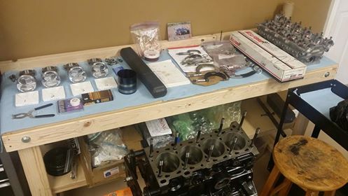
So I have the long block together and the new cams timed.
This is what I started the day with
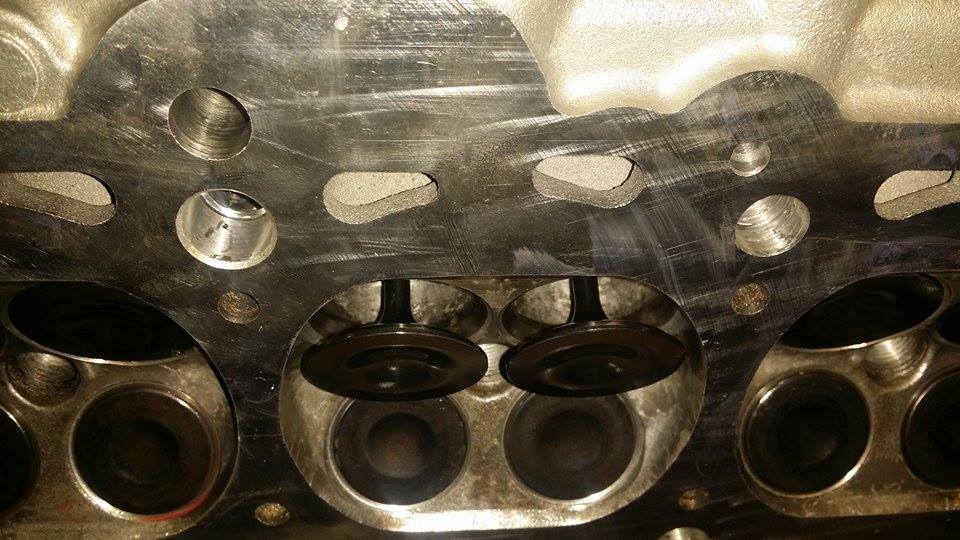
This is why I had to be so worried about timing, piston to valve and valve to valve clearance.
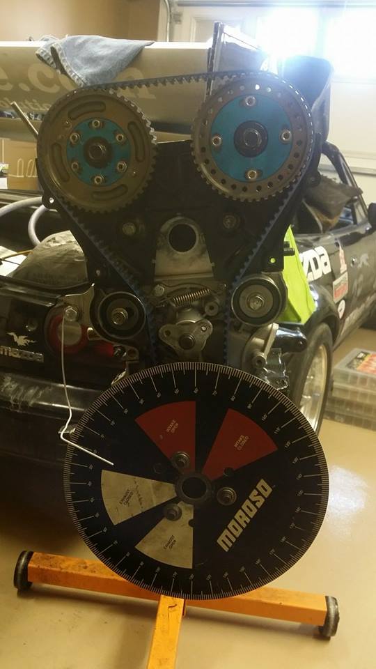
Getting the cams timed per the cam card. I'll finalize the timing on the dyno.
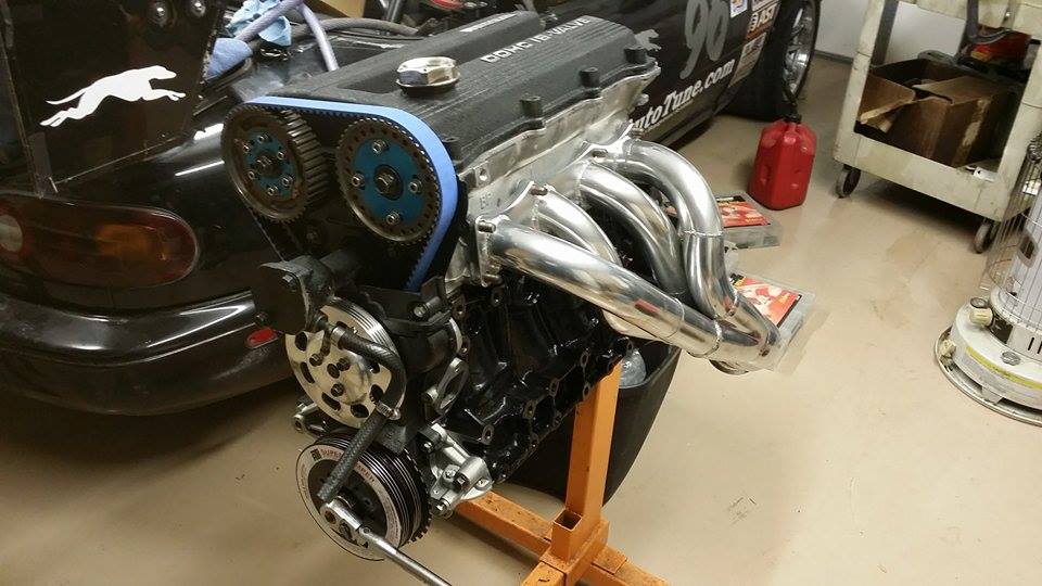
And here it is at the end of the day. Still have a few things to take care of today....but should have it ready to go in the car by tonight.
This is what I started the day with
This is why I had to be so worried about timing, piston to valve and valve to valve clearance.
Getting the cams timed per the cam card. I'll finalize the timing on the dyno.
And here it is at the end of the day. Still have a few things to take care of today....but should have it ready to go in the car by tonight.
Reply
0
0


Elite Member

Joined: Jul 2005
Posts: 2,502
Total Cats: 146
From: Anacortes, WA
They look like nice Ebay cam gears direct from china I got a set as well.
Reply
1
1
Thread Starter
Joined: Jan 2011
Posts: 1,234
Total Cats: 283
From: Chattanooga, Tn
I'm trying to get it ready before the Blytheville Pro Solo. (if it happens) if not...the Dixie National Tour.
I spent the evening in the garage doing some additional work on the cams. The cam card that came with them have all the timing events listed at 1mm of VALVE lift. I found this somewhat confusing as all domestic cams are rated at .050" CAM lift and "seat to seat valve events." so I got the degree wheel back out and the dial indicators and measured all the events from seat to seat at the valve.
I really have no idea what to expect from these cams.....but I have a feeling it will be extreme one way or the other
Reply
0
0

Junior Member
Joined: Mar 2012
Posts: 149
Total Cats: -2
From: Searcy, AR
I'm trying to get it ready before the Blytheville Pro Solo. (if it happens) if not...the Dixie National Tour.
I spent the evening in the garage doing some additional work on the cams. The cam card that came with them have all the timing events listed at 1mm of VALVE lift. I found this somewhat confusing as all domestic cams are rated at .050" CAM lift and "seat to seat valve events." so I got the degree wheel back out and the dial indicators and measured all the events from seat to seat at the valve.
I really have no idea what to expect from these cams.....but I have a feeling it will be extreme one way or the other
I spent the evening in the garage doing some additional work on the cams. The cam card that came with them have all the timing events listed at 1mm of VALVE lift. I found this somewhat confusing as all domestic cams are rated at .050" CAM lift and "seat to seat valve events." so I got the degree wheel back out and the dial indicators and measured all the events from seat to seat at the valve.
I really have no idea what to expect from these cams.....but I have a feeling it will be extreme one way or the other
Reply
0
0


