When you click on links to various merchants on this site and make a purchase, this can result in this site earning a commission. Affiliate programs and affiliations include, but are not limited to, the eBay Partner Network.
thread tangent....
i recently bought a 4'x12' sheet of 1/8" aluminum from jim downing for a trailer i'm building. mr. downing has a BIG BOY race shop. reason for mentioning it here? he was the first to put the m45 on a miata.
youtube video of his shop (it's better in real life than in the video). https://www.roadandtrack.com/car-cul...ry-collection/
I've actually got about a million more pics of the process, everything from cleaning to repacking the needle bearings, etc, but I didn't feel like this was the right forum to post a "how to service your M45" thread :P
Although the internet could use one. There's one video on youtube of some caveman with a Honda MP62 based kit who splits the housing, and he does so by driving screwdrivers through the sealing surfaces with a hammer. What the ****. Then he blasts the needle bearings with generic white lithium grease. Barf. Pretty sure that blower didn't last long after that. If this one goes **** up I might consider sending it to Jon Bond Performance for a full refresh (seals, bearings, etc) but right now it feels great so I'm going to let it ride.
But yes, I also find cleaning things to be therapeutic, in a way. Also, not gonna lie I was in a lot of pain and on a lot of opioids at the time that all got cleaned up and went back together. Hah!
Originally Posted by portabull
thread tangent....
i recently bought a 4'x12' sheet of 1/8" aluminum from jim downing for a trailer i'm building. mr. downing has a BIG BOY race shop. reason for mentioning it here? he was the first to put the first m45 on a miata.
youtube video of his shop (it's better in real life than in the video). https://www.roadandtrack.com/car-cul...ry-collection/
Yep! The Downing Atlanta M45 based supercharger kits for the NA6 Miata came from him originally. Then I think Jackson Racing bought the rights, made some changes to work with the 1.8, and eventually sold the rights to Moss. It's been an adventure sorting all this stuff out. Lots of information on m net, and even more broken links. But thanks for the video
Got my TPS harness hacked in today. Yay Deutsch connectors! Now I just need an actual Deutsch crimper and I'll be a happy camper.
It hurts my soul to cut off a factory connector, but at least its not scotch taps or butt connectors. I bought a replacement TPS Connector Kit from Ballenger so I can always go back if need be. Provided there's enough extra harness length in that location...
Also got some fuel management (of a sort) installed today.
The CARB EO for D-453-5 includes language about "a new fuel pressure regulator" which happens to be a Jackson Racing Rising Rate Fuel Pressure Regulator. My kit did not come with one, so I had to do some wheeling and dealing in forum classifieds here and on m.net to see what people might have kicking around. My JR FPR came from a guy in Florida who had helped a friend upgrade from it to a Megasquirt on his NA6. JR FPR is JR FPR as far as Moss is concerned so I made the deal and aware we go. These aren't exactly available new so I'll take what I can get.
I've seen reports that these JR FPR things are set to 5:1 (5psi of fuel pressure per pound of boost) but I can't find any documentation from Moss or JR to back that up, just various old forum posts which may be tribal knowledge. In order to make sure I'm not doing something incredibly stupid, I bought a Fuelab 0-120PSI 1.5" Fuel Pressure Gauge and 5/16 Inline Fuel Pressure Gauge Fitting from Summit so that I could keep an eye on fuel pressure. I have some experience with the Fuelab stuff as I used it on the NB fuel system, so I didn't mind spending a couple extra bucks for known quality. All hoses were 5/16ID Gates Barricade Greenshield with a 225psi working pressure and clamps are Vibrant Fuel Injection Clamps for 5/16 ID hose.
Plumbed it in, fired it up, and it ran! Nice!
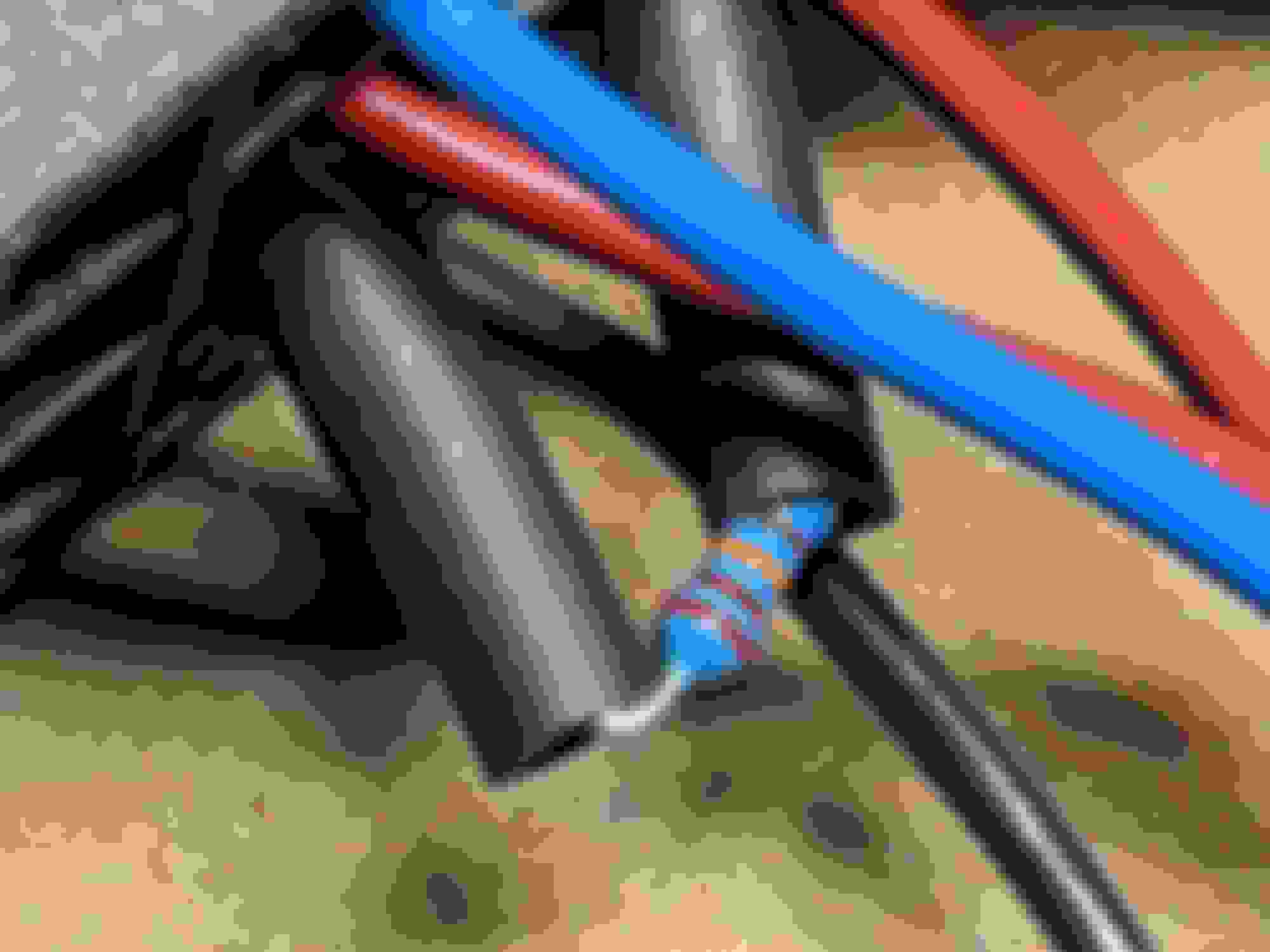
I turn my back to grab some vacuum hose and lo and behold, a lake of ******* fuel appears! What the hell! It looks like its coming from one of the hose connections at the gauge, so I shut it down, disconnected the battery and tightened the clamps. Started it up again and now its gushing. Sweet jesus. Shut it down again and start disconnecting things when I noticed this:
Here it is from a different view:
This is not a liquid filled gauge. Goddammit. Confirmed its the gauge by hooking it up again and watching fuel absolutely pour of of the body. /sigh. Soooooo glad I bought the nice one. Need to remember to call Summit tomorrow and get my Karen on.
Fortunately, I have a spare...
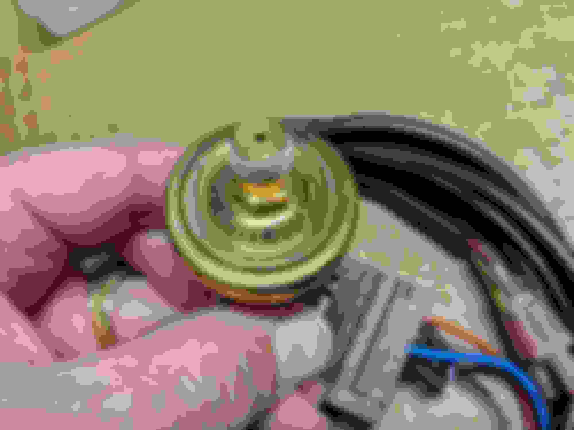
So after robbing the one off the NB fuel system I was back in business. After getting in plumbed in I went to go set the base pressure on the regulator...
Sonnovabitch!
Turns out the guy I bought this from had probably had it sitting on a shelf in his garage for years, and the diaphragm inside is shot, looks like dry rot. I'll shoot him an email but I'm not expecting a lot from FloridaMan on this one. I'm not going to be surprised when he responds with "Oh yeah, it leaks. That's why we replaced it"
So I put it back together and hurled it into the sun.
Then I pulled out the second JR FPR I picked up off the classifieds and installed it.
Because if its worth having one, its worth having a spare. I'm not sure this one has ever been installed. The hoses and hardware are still in the bag and it doesn't smell like fuel.
Look ma! No leaks!
Looks like its holding about ~46psi with the vacuum line disconnected. And yes, I oriented the hose so you could see the CARB number There's no spec in the instructions for base pressure (of course) but general consensus from the forum archeology I've been able to do is 45-50psi sans vacuum signal is appropriate. Some people claim that higher pressure helps with lean tip in but we'll see.
The last hardware install step, which I have yet to complete, involves what the instructions call the "Idle Compensator Module" as described on pages 7-8 of the Installation Instructions (attached here as 999-100.pdf)
By some stroke of luck or fate or karma or whatever, I actually managed to find one of these things still in the factory package.
To be perfectly honest, I had no idea what it was and neither did the seller. There's no BOM or manifest on the damn instructions so its not like I could have even guessed. I believe they had it listed as "maybe an oil pressure sender?" and I asked them to throw it in thinking maybe it would be useful.
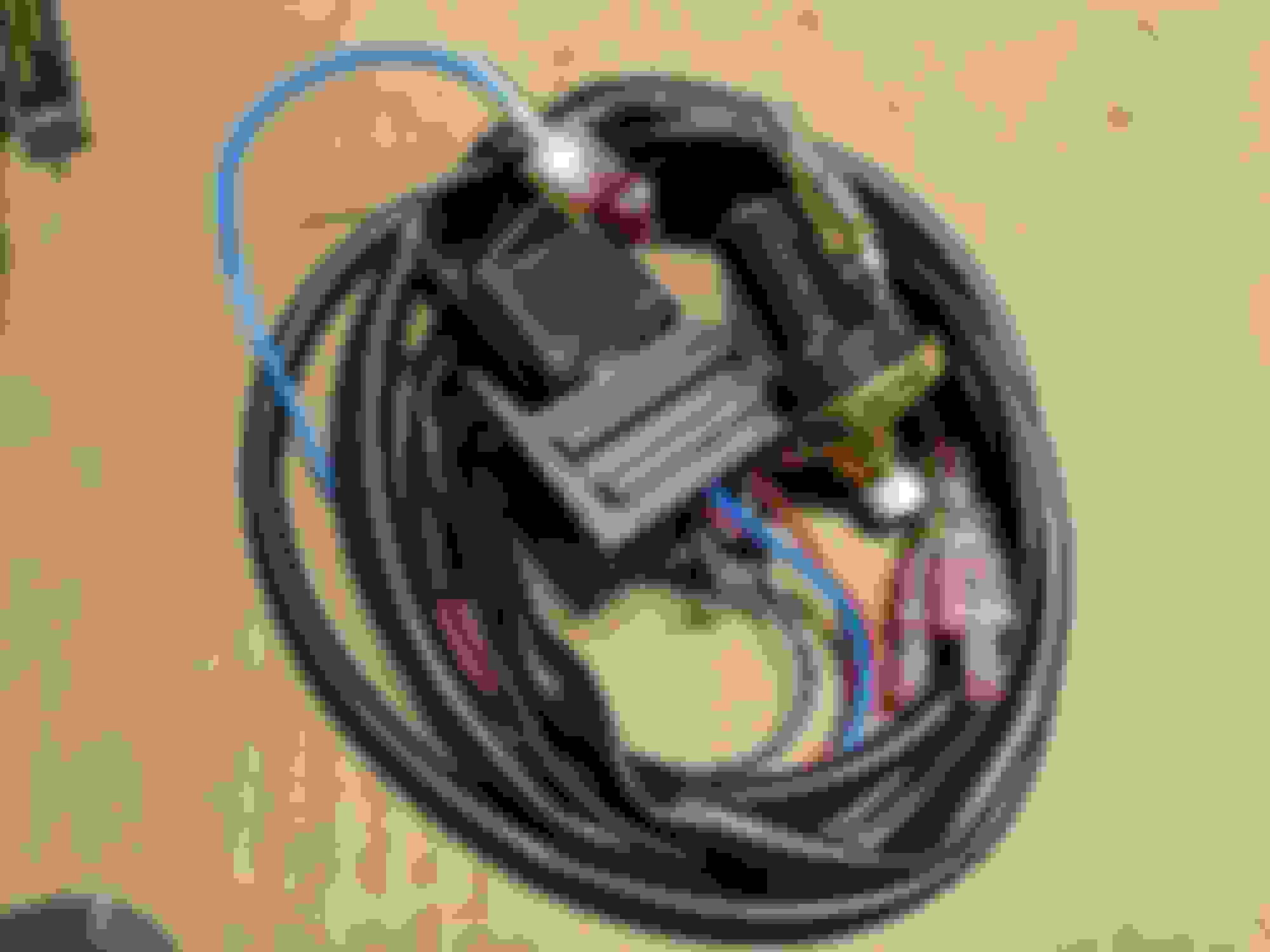
It turns out the "Idle Compensator Module" is nothing more than a relay, relay socket, Hobbs pressure switch, a resistor, along with some wire and connectors.
Looks to me like red, red, orange, brown? So 22kΩ �1% tolerance. Based on size I'd say its 1/4 watt.
Looks like an SPDT 30A relay?
The instructions have you screwing the Hobbs switch into the side of the dummy throttle body, then using the vampire tap <shudder> to tap into 12v from the windshield washer plug, and running 2 wires over to the MAF connector clear on the other side of the engine compartment. You cut the center wire to the MAF and attach the 2 wires to the ends you just cut. Again, better description on pages 7 & 8 of the attached PDF.
11/21/20 Edit: It appears I got this wrong, see post #236 below for fuckery
As near as I can tell, when the Hobbs switch sees boost, it trips the relay and sends the center wire of the MAF through the 22kΩ resistor. Center wire on the MAF is IAT for the NA, so what the hell is going on here?
So if this was adjusted to trip as soon as there is any positive manifold pressure, this "Idle Compensator Module" would be telling the factory Miata ECU "BITCH, ITS COLD AS A MOTHERFUCK UP IN HERE" and I suspect the ECU then starts throwing extra fuel because -20� air is going to be xtra thicc and we're going to want more fuel to compensate. Now this is not enough fuel for boost, but it DOES put the put the ECU in a state where it expects a rich condition on the very narrowband o2 sensor.
...and then the JR FPR starts jacking up the fuel pressure causing our injectors get hella swole. Neat!
Now this is all speculation on my part, I'm just reverse engineering this based on what I'm seeing in front of me and stock ECU logic as I understand it. Again, just speculating here but this seems like what the classic o2 clamp does but instead of lying to the o2 sensor input to be blind to the additional fuel, we are lying to the IAT input and having the ECU increase injector pulse width for us, while also expecting a rich condition. This is reported to help with the classic JRSC lean tip-in issue, but I guess the proof will be in the pudding. The 30A relay is MASSIVE OVERKILL for something like this, but I guess if you need that functionality you buy what is cheap rather than what fits.
I'm not vampire taping this into the windshield washer motor when there is a perfectly good fuse box in that same corner of the engine compartment with unused AC fuses in it, and I'm not going to cut up the MAF harness either. In fact, I bought a new 5 pin MAF Plug Kit in order to fix the damage already done, and then I bought a second 5 pin MAF Plug Kit AND a matching 5 pin MAF Receptacle Pigtail so that I can make a shorty 6" MAF extension and then tap into THAT wire, rather than causing more havoc in the factory wiring. There's absolutely no reason your engine compartment should look like a shitshow of butt connectors and vampire taps. This **** isn't hard, you just have to be patient and plan things out.
Last edited by EO2K; 11-21-2020 at 03:55 PM.
Reason: Clarification, added video
About the only large part I can't seem to be able to find from the original JRSC kit is a damn crossover pipe. I know someone has one sitting on a shelf in their garage after they installed a TDR Intercooler, but so far I haven't been able to find one. I've emailed Moss and again, Gary at TrackdogRacing.com, but unfortunately nobody has one around. I'll have to drop some WTB threads on CR, M net and here on MT and see if I can scare up something. I've been watching eBay, OfferUp and Craigslist as well and so far no love. /sigh
After just finishing what I thought was a PITA install of an M45 on a friend's car, I can't imagine going through the extra bullshit you've chosen to put on yourself.
I can say that even not intercooled and on TDR fuel cards, M45 NA8s scoot pretty good lol.
After just finishing what I thought was a PITA install of an M45 on a friend's car, I can't imagine going through the extra bullshit you've chosen to put on yourself.
I can say that even not intercooled and on TDR fuel cards, M45 NA8s scoot pretty good lol.
When he decides to put an intercooler on it you should have him sell me the crossover pipe The Trackdog Racing one seems pretty legit.
Or when he decides to go turbo he should sell me the whole thing so I have more spare parts
I know I've mentioned it a couple of times but I've some belt problems. Which of course it does, because its a stupidcharger.
If a picture is worth a 1,000 words, a video is probably worth a million. Pay close attention to where the belt rides on the two idlers
Here's a still frame
Take a look at the relationship between the edge of the belt and the edge of the passenger side idler pulley (top of above image) and the driver side idler pulley (bottom of the image.) The pax side idler is fed from the crank so its tracking pretty much where it wants to be. The driver side idler is being fed from the blower and it's also tracking where its being fed. Clearly we have a problem.
If I crank the tension adjuster almost all the way to the end of its range it'll hold the belt on the pulley, but just sitting there at idle it'll shear little flakes of rubber off the belt. It's also going to **** the bearings in the blower because that's a TON of tension. No bueno.
I showed the blower mounting bracket previously in the thread but without knowing what you are looking at they probably don't make sense. Here are some pics of what the main mounting bracket looked like when it came from Moss, I stole these from various FS threads here and on m.net:
Center of frame you can see the gold cad plated steel mount. Its actually 3 pieces. Those two "ears" go over exhaust manifold studs
Here is the mount with the triangle section with the exhaust stud holes not included. You can see the round fastener with the internal allen hex in the short angle piece on the right edge of the bracket. The threaded section of that fastener passes through all 3 parts
Right side of the frame here is the triangle piece with the 3 holes.
Good clean shot of the main bracket and the triangle. The slotted hole should allow for some fore/aft adjustment of the blower.
As things sit now, I've clearly got an alignment issue. Using a 6mm allen key as a straight edge we can sight down the face of a blower pulley...
And we can see exactly where our problem lies. Projecting the line down the center of the allen to the edge of the belt on the idler you can see we are at least 3mm off. Why 3mm? Well, that's half the width of the allen wrench
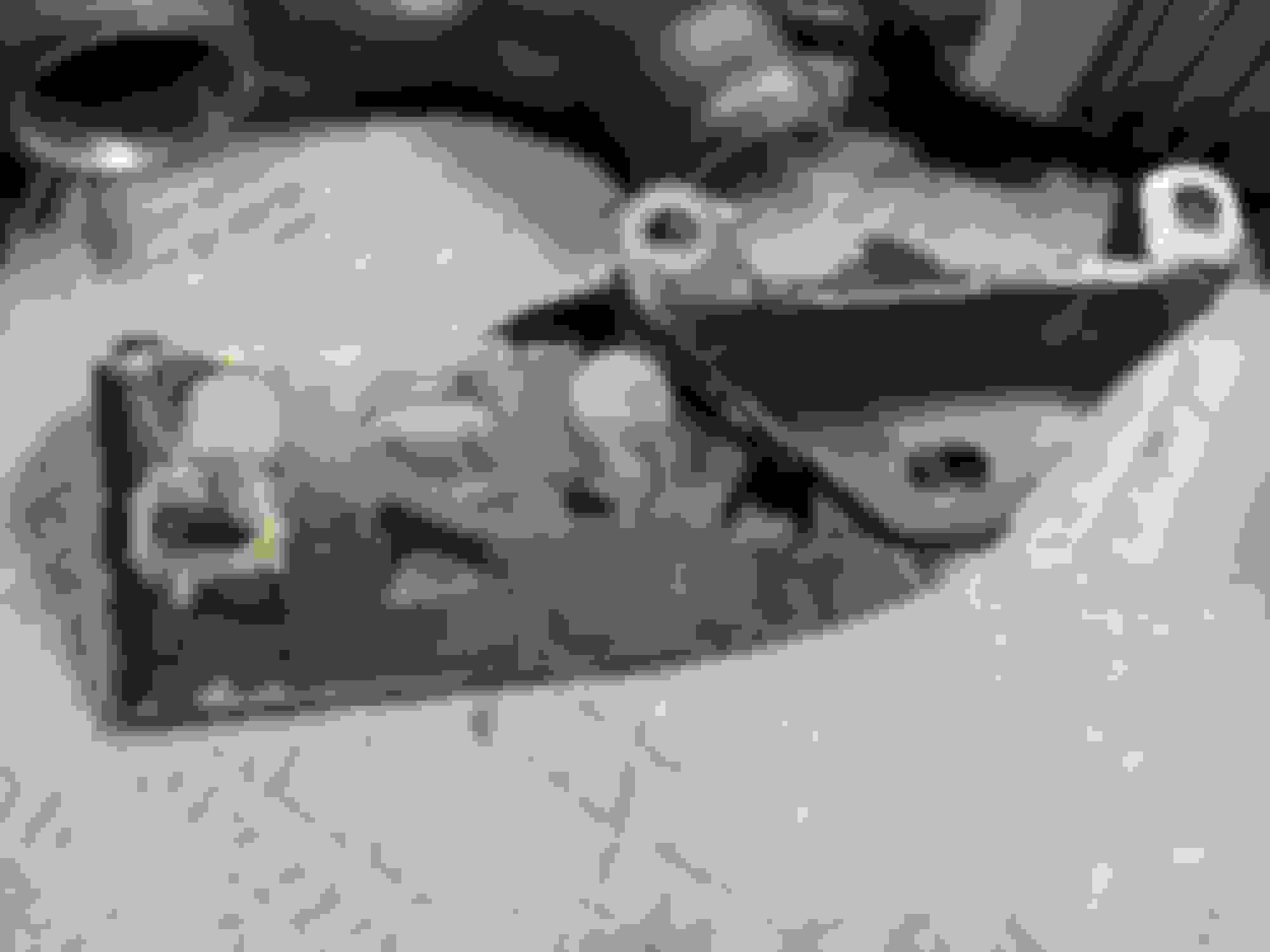
So now here is my mounting bracket:
As you can see, my 3 piece bracket is now a 1 piece bracket thanks to some fuckstick with a welder. My assumption is they lost the tapered bolt and decided to "fix it" with the hot snot gun rather than wait for a replacement part.
The two above pics plainly show the taper where that big allen driver fastener was supposed to live
They were certainly through. When all you have is a hammer everything looks like a nail. Just because you have a welder doesn't mean you should weld everything.
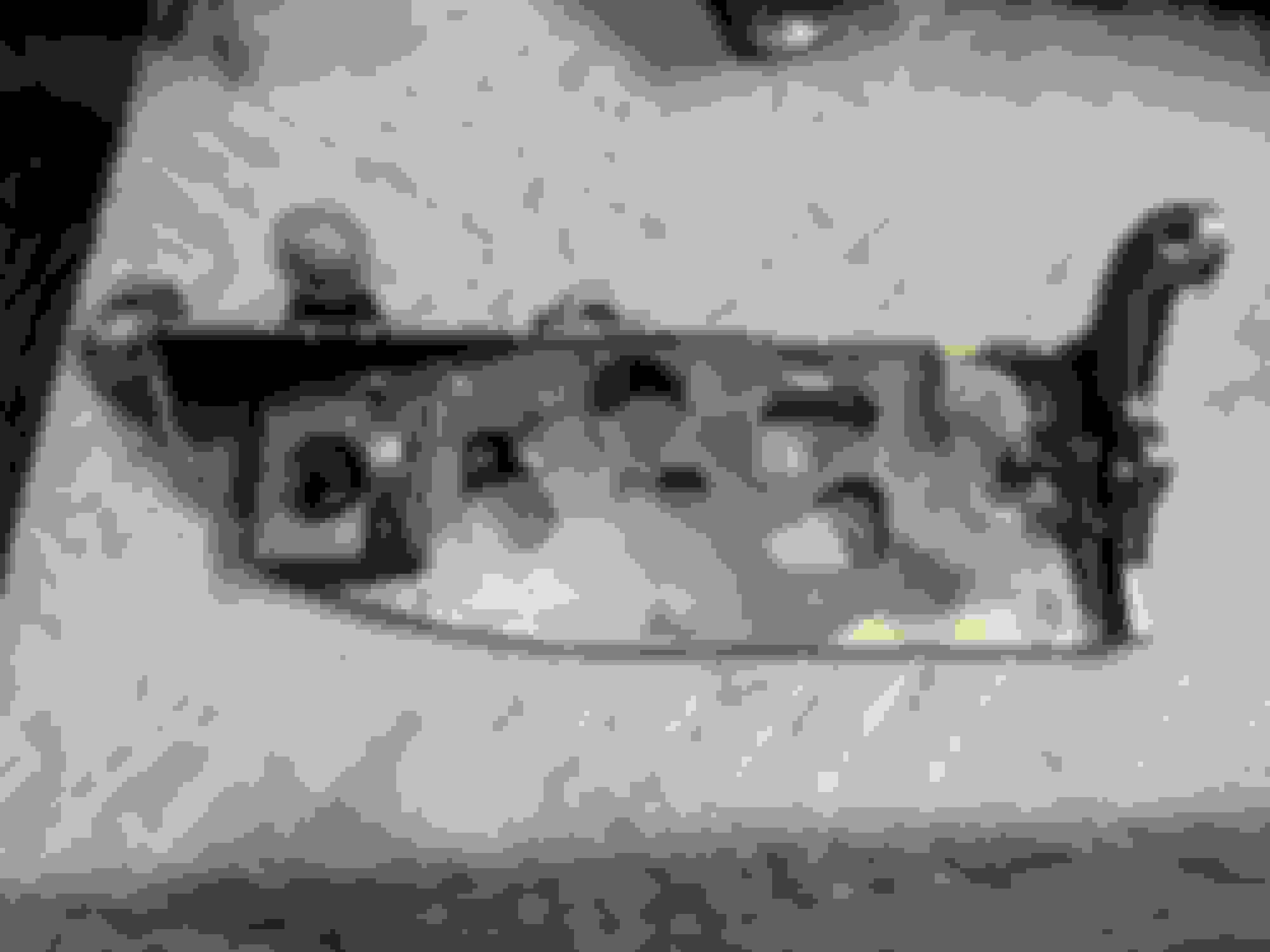
And wouldn't you know it? There's the 3mm of fore/aft adjustment I need. ************.
Clearly someone before me had this same problem because the exhaust stud holes are not exactly round anymore.
This is ... frustrating. As I see it I've got a couple of options here:
Cut the welds out of the bracket and try to restore it to adjustability.
Elongate the holes even further
Make a 3mm spacer to fit between the nose pulley and the shoulder on the blower input shaft
Option one is a shitload of work. If whoever weldfucked this thing together got any kind of decent penetration (giggidy) its going to be a lot of effort to cut it apart and then smooth it back out again. I don't have welder to refill the inevitable damage I'll do with the cutting wheel.
Option two can be accomplished with a die grinder or a rat tail file, but I'm a little worried about the amount of material available in the backside of those eyes.
Option three involves removing the pulley which shouldn't be a big deal as people remove these things to change pulley sizes all the time. I have a lathe so spinning up a spacer is easy enough but I need to make sure there is enough additional thread hanging out of the nut.
Right now I'm leaning toward a combination of two & three. Tomorrow I'll pull it apart yet again and see if I can pull it forward with a clamp or something to bias it as far forward as possible and measure those lower mounting holes to see what I can get away with.
Man the level of coincidence is insane for me today.
>PM from EO2K about my big black bent pipes, email notification
>Email notification that 30' Black electrical conduit order for work shipped
>EO2K Updated thread, mentioned Ballenger Motorsports
>Ballenger replied to an email I sent a week ago regarding a special order connector
In post #223 above I described what I thought was the theory of operation for the "Idle Compensator Module" for the JRSC, the doodad with the relay, Hobbs switch and resistor. It turns out I was not entirely accurate on that...
My morning started fairly chilly.
As everything was freezing this seemed like a good time to do wiring. Good thing cars are generally self-warming.
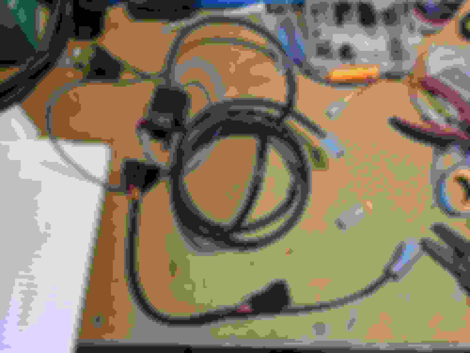
This business has been bothering me for a while so I decided it was time to fix it.
Take good notes and then snippy-snip
Crimpy-crimp
And jam it all back together. A piece of 3M Super33+ electrical tape on the sleeve really ties the room together. Job done!
Once again, everything I touch that's electrical gets a dab of the Dow Corning #4 upon reassembly.
As long as my hands were already numb from the cold it sounded like a good time for more electrical modz:
On the 94/95 Miata the engine cooling fan and the AC fan are triggered by the ECU, and it does so by dropping the trigger to ground to activate the relays. The trigger for the main cooling fan is 1L and the AC fan is 2S. By splicing the wire from 2S into 1L we now have both fans running at the same time. AC fan is still fused through its OE fuse and activated by the OE relay so no additional components are required. Neat!
This of course requires you to still have the AC relay, fuse and fan in place so if you tossed those after you removed your AC, you are out of luck. Personally I'm just thankful the AC fan motor was still good. The boomslang-esque ECU extension harness originally came from TrackdogRacing.com (you can find it here on their site) although mine came second hand.
OK, back to the Moss "Idle Compensator Module"
As I explained previously I didn't appreciate the hack-n-slash butt connecter madness that Moss included with this widget, so I made an extension and spliced it in there.
Deutsch DTM connectors are probably my new favorite things. I also made a little plug to bypass the fuckery should it become an issue. Although I guess I could just remove the extension... but I already had the connector on there so meh.
The relay is one of those little bastards where the 30/87 is normally open, there is no 87A, and both of the 87 terminals are tied together inside the relay. When you pass current through 85/86 then 30/87 closes and completes the circuit instead of the traditional 30/87-30/87A flip flop when triggered. I think these are only used for horns. It also turns out that I had the Hobbs switch backwards, its actually a normally closed switch. Here's a quick diagram of what Moss ships:
Apologies as I'm no BigClive, but I think it'll make a solid visual aid
Here's my revised bullshit theory of operation:
State1: Engine under vacuum
The Hobbs switch is in its normally closed state thus energizing 85/86 coil. This allows the IAT signal to pass from 30 to 87 with no modification. (The resistor is ignored)
State2:
Under boost, the Hobbs switch breaks the ground signal and the 85/86 coil is de-energized. The 30/87 circuit is broken however our old friend the 22kΩ resistor is now completing the IAT circuit between 30/87 and providing its resistance in series with whatever the IAT is reading.
So in short <rimshot> we are still lying to the ECU and making the IAT say "Its cold as 10 ************* up in here!!!" when the engine goes into boost, its just doing it in a different way than what I originally expected.
Something that strikes me as quite odd is the choice of relay. These horn relays aren't exactly common and I haven't seen one in probably 20 years. In a traditional generic automotive relay, the 30/87A circuit is NC (87A post is traditionally in the center position) and it flips to 30/87 when energized. If you were to exchange the included horn relay for a generic automotive relay you would start with the IAT disconnected (because 87 isn't populated in the Moss relay socket) and that would earn you a CEL/MIL. As soon as the engine went into boost the relay would flip back to its de-energized position and your CEL/MIL would go away, but you would get no benefit from the 22kΩ resistor.
Also, this FIAMM horn relay that was supplied in the kit is garbage. You can't pull it out of the socket without ripping off the cover, and it is in no way weather tight. If I mount it in the recommended location its going to get rained on through the gap at the edge of the hood and probably won't last long once its wet. I'll try to come up with something else but in the mean time, this one will have to do.
Why do you resist? We only wish to improve quality of life, for all.
So after doing some more reading last night it turns out ZEE GERMANS used a lot of those NO/conjoined 87 type relays in 90s things, particularly BMWs, for stuff like vehicle lighting. On my next trip to the junkyard I'll see if I can find an E30 or something to poke around it and grab a few. Whatever BMW used, even if its 25 years old at this point, has got to be better than the hot garbage FIAMM relay that Moss shipped back in the day.
And it is quire literally hot garbage. It was like 50�~55� ambient while I had it tied in to 12vdc source for testing and the thing got uncomfortably warm to the touch.
Which I guess is good because its IP rating is probably something like IP41, maybe IP42 if I'm being generous. The heat generated during operation is probably beneficial in helping purge the moisture that will undoubtedly ingress into the relay while mounted horizontally under the hood.
To this day this is still probably one of my absolute favorite "OEM+" mods to the car:
That's the result of the OE Mazda Canadian Daytime Running Light Module PN NA07-67-750A. I picked mine up for around $40 shipped about a million years ago, apparently they are over $100 now from dealer sources. An enterprising individual north of the border could start harvesting these from junkyards and make a little pocket money as the m.net folks are apparently still on the lookout.
Also grabbed an OG Voodoo (Team Voodoo?) shift **** from someone's part-out. I always wanted one of these things back in the day, and now I have one! This is pretty close to Peak miata.net, about the only thing better/worse would be a set of caliper covers It's a little beat up but it was also cheap. Quite fitting for the car, really. I'd love to find one of the matching ebrake lever covers but I'm not going to hold my breath.
 11-11-2020, 11:12 AM


 1
1


 There's no spec in the instructions for base pressure (of course) but general consensus from the forum archeology I've been able to do is 45-50psi sans vacuum signal is appropriate. Some people claim that higher pressure helps with lean tip in but we'll see.
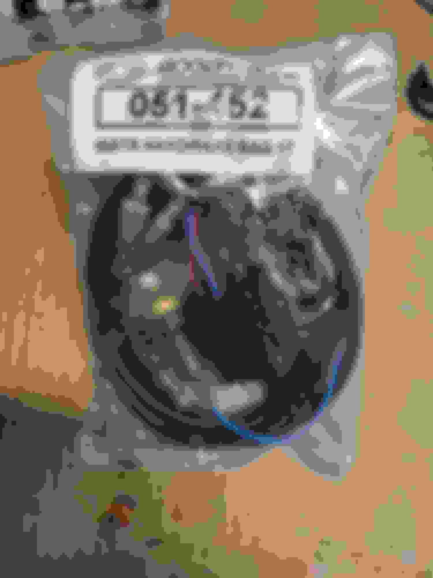


 The Trackdog Racing one seems pretty legit.