
In Soviet Russia car build YOU!


woah. That's pretty shitty. I guess you didn't check battery voltage with old alternator?
I've had issues with the MS3 voltage readings in the past, found out I hated their math, but after I fixed a dumb wiring issue (transistors used to drive dash LED's) enough of it went away I could live with it.
Like all things megasquirt - if the car runs, no one cares why it doesn't work right.
Glad this is coming together for you. Guess I should get a sender as well. :-)
Reply
 0
0

0
The problem came back, now its reading 1V low.
Measured VRef and its 4.9V. I'm going to look into the wiring and ask on msextra.
Any thoughts on upgrading U5, though? Its 500ma in stock form and if I'm going to use VRef to drive a bunch of sensors, I probably want more current than that.
Measured VRef and its 4.9V. I'm going to look into the wiring and ask on msextra.
Any thoughts on upgrading U5, though? Its 500ma in stock form and if I'm going to use VRef to drive a bunch of sensors, I probably want more current than that.
Reply
0
0
That's not a terrible thought. I guess you could unplug a couple sensors, see if it gets better. :-) You'd think most of the measurements would be as-a-function-of the 5V being fed them, but yeah, then wiring would mean different sensors are getting a different voltage, and things all around would be bad.
Not sure why the MS is seeing the wrong voltage, though - that's a sign of something else. I did figure out it can't really read the right voltage since the circuit it uses... But I think it's off by less than a volt. Anyway, it seems easy enough to pull that chip - or bypass it temporarily to see if things improve.
Not sure why the MS is seeing the wrong voltage, though - that's a sign of something else. I did figure out it can't really read the right voltage since the circuit it uses... But I think it's off by less than a volt. Anyway, it seems easy enough to pull that chip - or bypass it temporarily to see if things improve.
Reply
0
0
The problem came back, now its reading 1V low.
Measured VRef and its 4.9V. I'm going to look into the wiring and ask on msextra.
Any thoughts on upgrading U5, though? Its 500ma in stock form and if I'm going to use VRef to drive a bunch of sensors, I probably want more current than that.
Measured VRef and its 4.9V. I'm going to look into the wiring and ask on msextra.
Any thoughts on upgrading U5, though? Its 500ma in stock form and if I'm going to use VRef to drive a bunch of sensors, I probably want more current than that.
Reply
0
0
You could upgrade L1 and L2 with a 4A equivalent. Not sure on a digikey code, I buy them locally.
I would highly suggest that you replace C16 and C17 with 33uF/50V aluminum electrolytic caps anyway.
C20 is irrelevant, C22 should be ok at 4.7uF, I don't think these sensors have any sort of transient requirements.
I would highly suggest that you replace C16 and C17 with 33uF/50V aluminum electrolytic caps anyway.
C20 is irrelevant, C22 should be ok at 4.7uF, I don't think these sensors have any sort of transient requirements.
Reply
0
0
To keep this thread going...
I finally got time to work on the car. I looked at the poor state of the wiring harness - it was modified so many times over the past 3 years... that I decided to redo it.
So far:

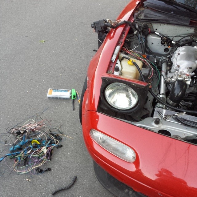
My approach is as follows: I'm keeping the chassis wiring mostly intact because it works and I don't care. Eventually I'll redo the chassis wiring as well.
As for engine wiring, I'm removing all traces of the current engine wiring and adding a new sub-harness. I'm also adding a separate fusebox just for the engine stuff.
I finally got time to work on the car. I looked at the poor state of the wiring harness - it was modified so many times over the past 3 years... that I decided to redo it.
So far:
My approach is as follows: I'm keeping the chassis wiring mostly intact because it works and I don't care. Eventually I'll redo the chassis wiring as well.
As for engine wiring, I'm removing all traces of the current engine wiring and adding a new sub-harness. I'm also adding a separate fusebox just for the engine stuff.
Reply
0
0


As for the connectors, I ordered from Ballenger and really I just got the TPS, IAC and CAS because they were old and shitty.
I have a total of 5 OEM mazda connectors remaining in my car
- NA CAS (using only 3 wires, tho)
- NA CLT
- NB TPS
- NB Idle
- NA8 Crank sensor
Everything else is some generic connector, lol
Reply
0
0
Reply
0
0
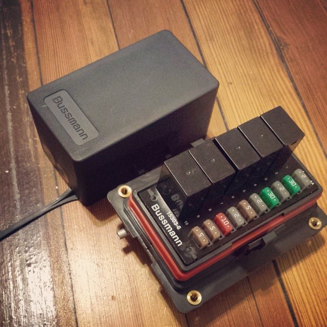
Metripack 280 Tangless, if I read correctly. Should crimp just fine in my open barrel uninsulated ratchet crimper. That box is cheap. And waterproof. I think I have another project to add on to my cars....
Reply
0
0
I have 5 relays which is more than I need but hey, might as well use them all. So, boost control solenoid and idle control valve get their own relay which will be switched on by MS when car is running - so it doesn't hum when car is off - I hate that ****. I'll write up a schematic later.
And, shouldn't boost also be off when pressure is negative? I wonder if you couldn't use a generic output to do that - I mean, over ride the output when RPM < 50.
Reply
0
0

With the AEM, i set the boost control line at atm pressure and below to 0% duty. no hum when the car was off/just cruising. solenoid will last a lot longer that way too LOL.
Reply
0
0
Good point.
I thought a bit more about the fusebox wiring and realized I forgot a bunch of circuits (cam/crank, O2)
I thought a bit more about the fusebox wiring and realized I forgot a bunch of circuits (cam/crank, O2)
Code:
Fuse		Amps	Relay	Relay 	Trigger
--------------------------------------
Ignition	2 Amp
MS3		5 Amp	Relay 1		Ignition
Boost/Idle	5 Amp	***
Cam/Crank	5 Amp	***
Spark		10 Amp	Relay 2		Ignition
Injectors	10 Amp	***
O2		15 Amp	***
Horn		20 Amp	Relay 3		Horn Button
Fan		30 Amp	Relay 4		MS3
Fuel		30 Amp	Relay 5		MS3
Reply
0
0


