When you click on links to various merchants on this site and make a purchase, this can result in this site earning a commission. Affiliate programs and affiliations include, but are not limited to, the eBay Partner Network.
Gotcha. I wasn't sure if these cores were direct from Laminova (available but no price on their website) or some chinese copy from source unknown, or from ebay/GM takeoffs. Thanks for confirming!
Gotcha. I wasn't sure if these cores were direct from Laminova (available but no price on their website) or some chinese copy from source unknown, or from ebay/GM takeoffs. Thanks for confirming!
No problem. Yep straight from Laminova. These are the 45mm diameter cores.
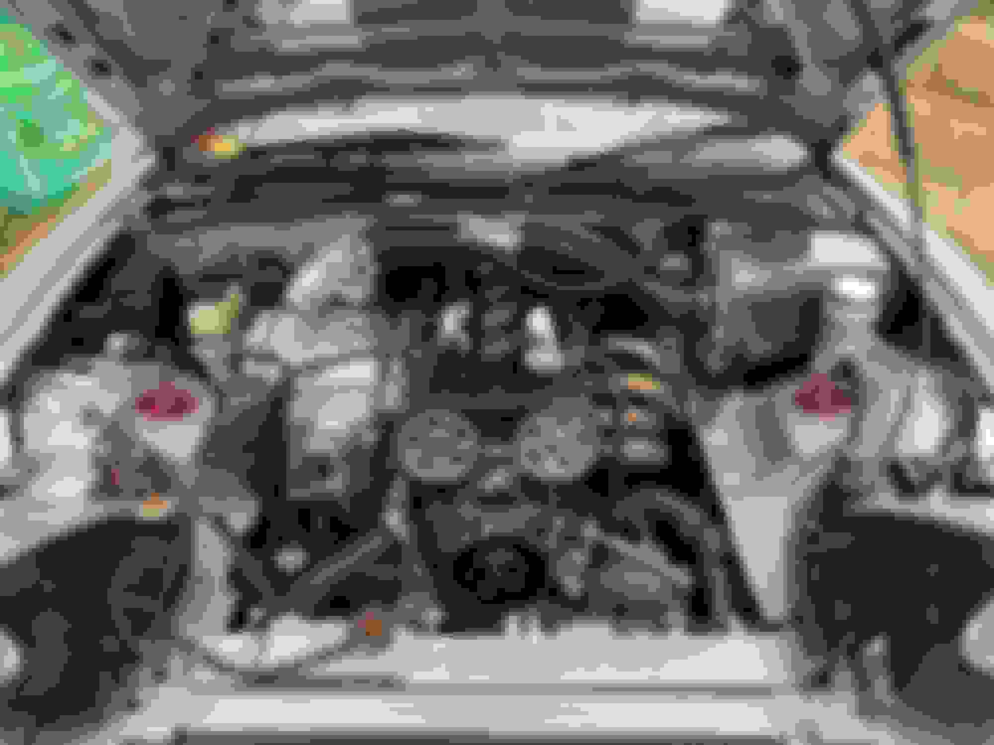
More progress, now at my favourite stage, seeing it on the mockup engine looking like a large aluminium fiddler crab, before the reality of trying to fit it all in the engine bay with an intake and throttle body sets in.
I pressure tested the cores at about 2bar, well over what it will see in service and the only issue it highlighted was a couple of pin holes in my welding to the AN fittings on the front cap (such a pita, all clean and double welded and still pinned, so glad the amount of welding in coolant related areas is really limited) but I have that under control now. The test equipment was a bit rigged up so I will order some better fittings and a valve so I can shut it off and leave it for a while, and read off a gauge to see if the pressure drops at all.
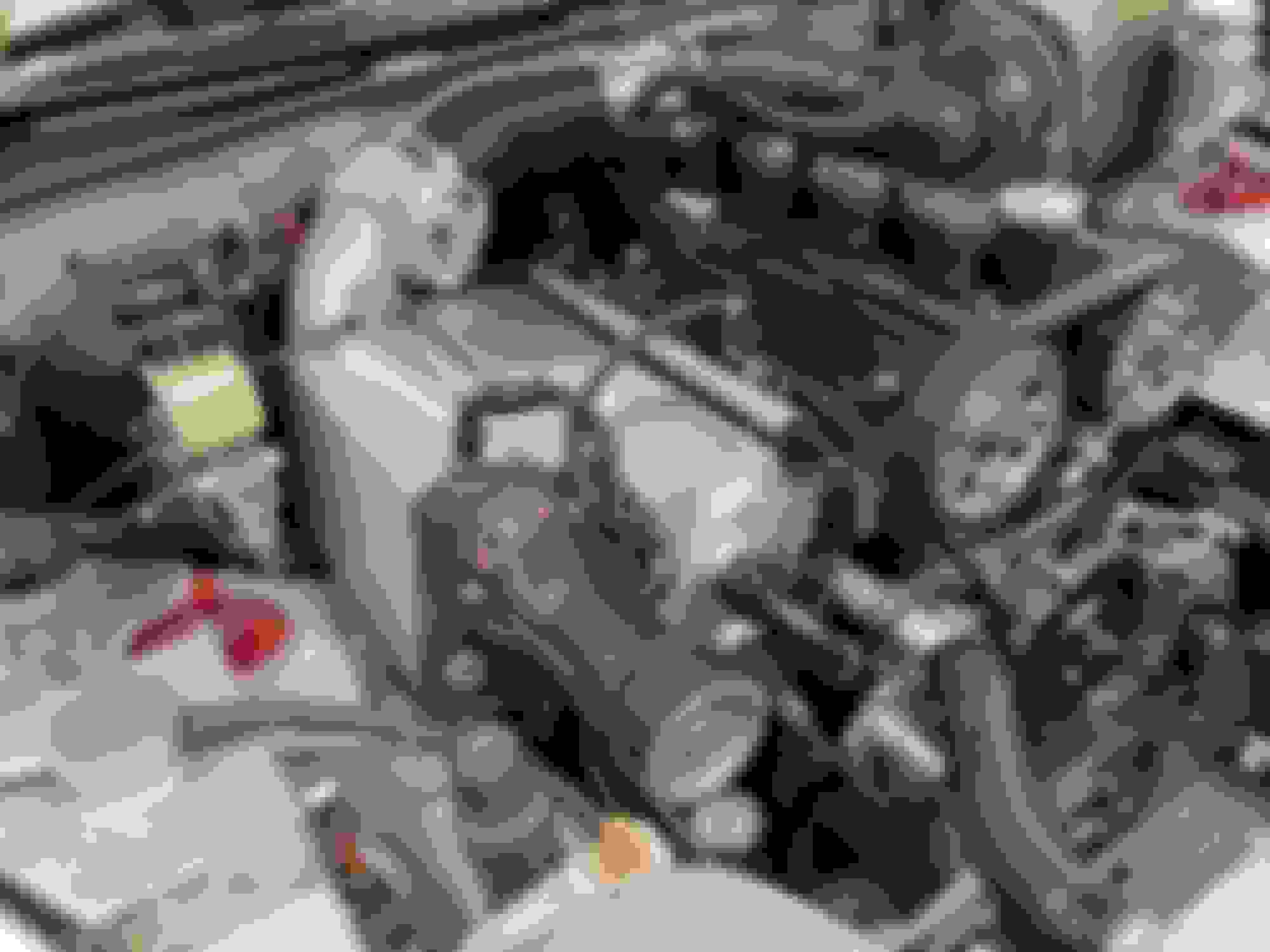
Bolted it all up to the manifold, then added the supercharger and I'm very pleased to report it is all plumb in line. Now onto making the support up from the block and the new intake.
Silly question, and a bit late too - I take it that you can't use a shorter nose and bring the blower forward, to allow more room behind?
Hey Gee Emm, ha ha yes a bit late now! But to be honest I like the outlet being pushed back more centrally, will help distribute the air more evenly across the cylinders. The room at the back isn't bad at all with the prop out the way anyway.
The tb needs to sit behind and above the chargecooler, then the intake duck down to the back of the sc, which is how it was before, it's not significantly different just the angle of the tb has to be relaxed to meet up with the intake pipework, this is because the whole chargecooler / sc unit is at an angle now rather than flat across the bay. My metalwork skills are better now too so I'm hopeful I can craft a smooth well sized intake, as it is so key to performance. No point having the bigger chargecooler if I just strangle the sc on the intake
Intake is going well. The central pipe section is made of 4 separate pieces then all welded together. The main difference over the previous intake is that is has a more rounded bottom section to turn the air more before the supercharger, and also expands more in cross section before the supercharger, which should increase pressure in that area.
I decided to file off the welds to give the impression it is made from a single piece on aluminium, which has come out ok although it did mean that fit up had to be absolutely spot on, as any leveling needs to come out of material thickness and you don't have much to play with. I did fill low sections by aluminium brazing / soldering with a MAP gas torch but I won't bother next time. The brazed material is a slightly different shade of grey to the normal aluminium and also because it does not actually homogenise with the base material there is a minimum thickness it gets down to then starts peeling off, which means it doesn't blend that well during filing / sanding.
Also all the sanding meant the weld to the sc back plate was a little grubby bit it went ok. Very happy with the weld to the throttle body flange that is real nice, smooth and uniform. I added an o ring groove to the tb flange as the old paper gasket had disintegrated (it is an aftermarket Mitsi Evo throttle) and I have been using rtv which is messy and then adheres the tb to the flange making it a pita to get off. It also likes to leak air through the bolts and whistle if you don't get the rtv right. This will be a big improvement in all of that.
Need to cut the opening out of the sc back plate, then smooth the inside of the welds a bit but nothing drastic. The fit up was good so there aren't any big steps.
On test fit all was good, pointing right where I need it, plenty of clearance to everything.
The amount of work and skill it takes to make parts look that good cannot be overstated. Very nice!
It's been a long time but back in 2016 or so I did pressure drop measurements and the air filter was a huge restriction on flow for my setup. I didn't have parts that flowed nearly as well as what you're putting together, but I can appreciate the work that goes into building an intake to flow really well. How big is that throttle body? I suspect going all the way to a 4" intake and TB would show gains IF the filter wasn't already a restriction.
Yeah you are right, the old filter was the big restriction in the intake, which was addressed when I built the big airbox and filter setup back in xmas '21. That netted the same results on the dyno as running a velocity stack straight into the throttle body, so I take from that that the intake in front of the throttle body is no longer any significant restriction to performance.
Throttle body is 70mm, which is sized nicely for the 3" intake tract. When I measured pressure difference across the tb it was negligible. I doubt there is really much to gain, but I needed to make a new one to sort out the fitment (old intake angled the tb into the valve cover on this setup) so may as well have a go at it
Still plodding along with it. The final bits and bobs seem to take the most time to come together.
The manifold is now 'ported' - smoothed out the rough steps from machining, added the various fittings and air temp sensor. Filled in the WI ports I had drilled and tapped.
Chargecooler cleaned out, built back up and pressure tested properly with a little valve / gauge thing with a fitting for my air compressor. Sods law with the silicone involved it took a few tries to get the thing to seal. For the first time the o rings on the cores played up. If you are not careful you can get them twisted and stuck. I think there is some optimisation to be done on the seats to make assembly more reliable but its R&D. I found you couldn't just rely on doing the caps up to seat them, the cores do need to be pushed into one end and you can feel them seat, then there was no issue.
Thought I had a nice easy solution to move my bias valve but it didn't work. I was trying to avoid having to remake the rear brake line but have now resigned myself to it. But should then have a solution.
The bypass pipework off the back of the inlet was too close to the brake booster. So have had to shift the angle a bit but that has led to further issues (silicone joiner contacting sharp edge of idle valve) so that may still need some fettling.
I've massaged the car to get room to drop the oil return out the bottom of the supercharger.
Made the support between block and supercharger. Couple of brackets, rod ends and a bit of tube. This is a far simpler and potentially less awkward solution than my old fixed support, I am just slightly worried about the joints pounding out, will just need to keep an eye out. Not sure if I am being over cautious there as in comparison to suspension loading the forces will be small. Has added benefit of being able to slightly preload the assembly to take a bit of the belt load stress off the manifold.
I might have it running by the end of the weekend, will see. I'm not in a mad rush.
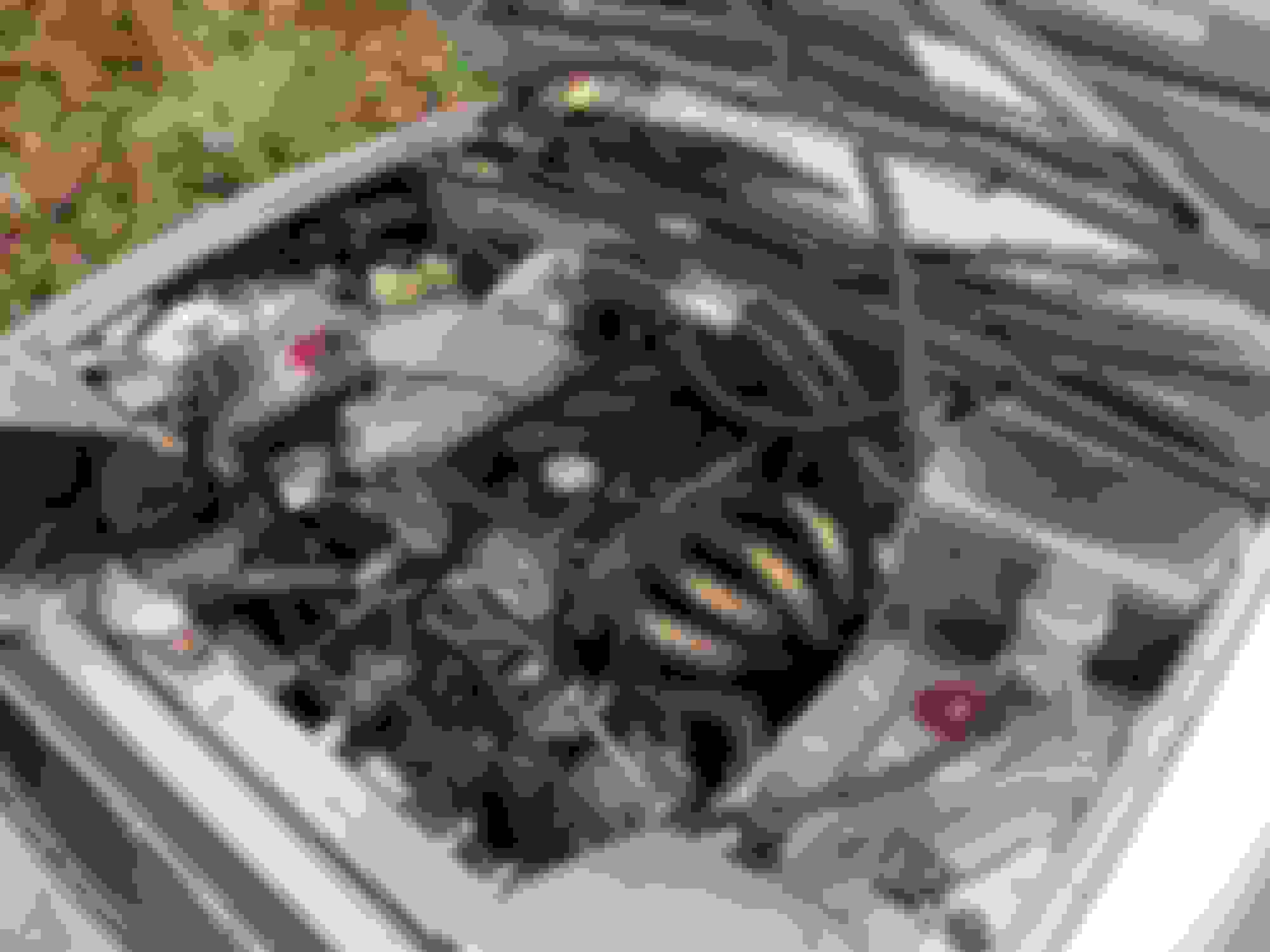
Got the car started up this morning. Few usual frustrations with bracket holes changing size once they are in inaccessible areas etc and making the new rear brake line / moving the bias valve was a bit of a faff, but it does appear to work! I took it for a 30min drive and all the fluids have appeared to stay in the areas they are designed to inhabit. The chargecooler works atleast as well as the old one (sounds silly, but there was a very real possibility in going backwards if the tolerances on things like the air guide tubes were too loose). I still have the old summer track tyres on and the weather has turned here now for winter, but signs in the datalogs are encouraging. I think it is running a little leaner (more air = good) and EGTs appear closer than before. Will get more data when the car is properly back on the road. But hey, I'm chuffed. The rod end support works really well and was a lot easier than the old support to bolt up. There is 0 movement when I tension up the belt now. I used to be able to just feel a slight movement on the old setup when I tensioned, we are talking fractions of a mm but you can feel it if you wedge your hand between the sc and the chassis. When I weighed the old vs new, dry the new setup is about a kg lighter, but it will gain a bit more when filled with coolant as there is another tube. I've forgotten what the actual values were it is on a note in the shed, just remember the difference.
Anyway, need to get the tyres swapped and also fix a rumbly rear wheel bearing. Then I'll start giving it some load to see where it is.
Got the car on track today. It is very stormy in the UK at the moment so it was a fully wet one, but I am happy to report the car was flawless all day.
Got a bit of data now too. The main difference the larger chargecooler / manifold has made is the pressure ratio the car now runs at. Where as before it ran a PR of just under 2 it now runs at about 1.85. It is quite interesting because temperatures haven't changed that much. The rate of increase of air temp has reduced by around half (which I am pleased with and bodes well for hotter trackdays) but I wouldn't say there has been a big shift generally in temperatures. This makes me think that this effect is actually the better ports on the manifold rather than the chargecooler.
I needed to add fuel to the map to get back on to target AFR, but this isn't that surprising with the PR shift - the MAP multiplier function in the fuelling calc is now lower, so I have had to add fuel to compensate, but mathematically I'm not burning more fuel in total.
These are 2x overlayed logs of pulls down the Curborough main straight. The slightly fainter one is from August, bolder one from today.
Note the barometer values - it was lower ambient pressure today which effects the fuelling and MAP values quite a bit. You get the PRs from MAP/baro, one is 1.99 the other 1.85.
This drop in PR should net me around 4-5bhp in lower sc drive forces.
Duty cycles are basically the same once you factor in the difference in baro, netting the same afr so I don't think I have increased mass air flow particularly.
MAT is lower today, not surprising given the lower ambient temp, but you can see the increase in temp during the 2 gear straight is far less today, 4deg vs 7deg.
Got the dyno later this month will see what that says. But very happy it all works as it should.
Ah so close to a full house! Developed a little issue today where idle speed was higher than normal. Wasn't doing it yesterday on the trackday, or on the drive home.
Anyway, I hooked up my leak down tester and the join between the chargecooler and manifold was leaking quite badly at the back. To be honest, there has been a slight whistle on this setup under vacuum since install, but I think the long trip yesterday broke a marginal seal. It was the excuse I needed to pull the whole lot off and give it a proper inspection.
I pressure tested the coolant circuit and that was perfect, which is the most important thing.
Looking at the sealing surface that was leaking air, there was a burr on the surface and I wonder if it was holding the components apart slightly and the silicone gave up with the hard use / long drive. I'm considering machining an o-ring groove in the chargecooler to do away with the silicone.
All good apart from that though, all good.
I don't think I am going to see a change in the MAP, pressure ratio or fuelling with this leak fixed because I think it happened after I had got all my data, but we'll see.
Well done! You have really optimized this build to be a top performer.
FWIW, on my build there are 2 things I have come to appreciate over time.
1. Using steel inserts on all the aluminum threaded holes. No issue with threads failing. I can torque the bolts
as much as I like. I can use fewer fasteners, because I know these will hold up. These inserts are what I use, but there
are many alternatives.
2. Cutting flanges for o-rings, when a custom sized flange is being used. On earlier installs, I made cardboard gaskets, and then I would
get lazy and just use silicone. It's nice when you have o-rings and know there is no way that that flange is going to leak, yet it is easy to disassemble if needed.
Both these items were more work up front, but paid me back by being much more reliable long term.
Those inserts look pretty sweet. I need to do a bit of digging on those and a solution available in the UK. I Heli-coiled the end cap bolt holes because they could not be that long or that numerous, aware of the weakness of small threads in ali. But I'm not a fan of the helicoils I have atleast (they are cheap ones). They seem to get stuck or crossed up when inserting quite regularly despite my best efforts not to. You probably noticed I put a lot of bolts across the top edge of the manifold. These are not helicoiled but are of a reasonable depth into non heat affected 6082 T6 ali. They are about 2x diameter deep so should be ok. You are right though, these steel inserts would allow a reduction in fasteners.
I'm enjoying the luxury of being able to machine o ring grooves. Far more professional, reliable and less annoying than silicone.
 09-27-2023, 03:23 PM


 0
0