When you click on links to various merchants on this site and make a purchase, this can result in this site earning a commission. Affiliate programs and affiliations include, but are not limited to, the eBay Partner Network.
I'm now happy with the top front of cylinder fitting. I had a realisation a week or so ago that it was probably going to be very difficult to bleed the coolant system, any air pockets having to make their way down into the block and out the front.
They likely wouldn't be that keen to do that and prefer to stick around in the top of the head, causing me cooling issues.
So the new fitting features a bleed valve (it's a bleed nipple for a Wilwood caliper). It has a small hole that feeds it that is positioned right at the top of the port in the head, and is seperate to the feed. So it should make bleeding nice and easy, just keep the front of the car up on jack stands tilting the nose up and run the pump with the bleed valve open.
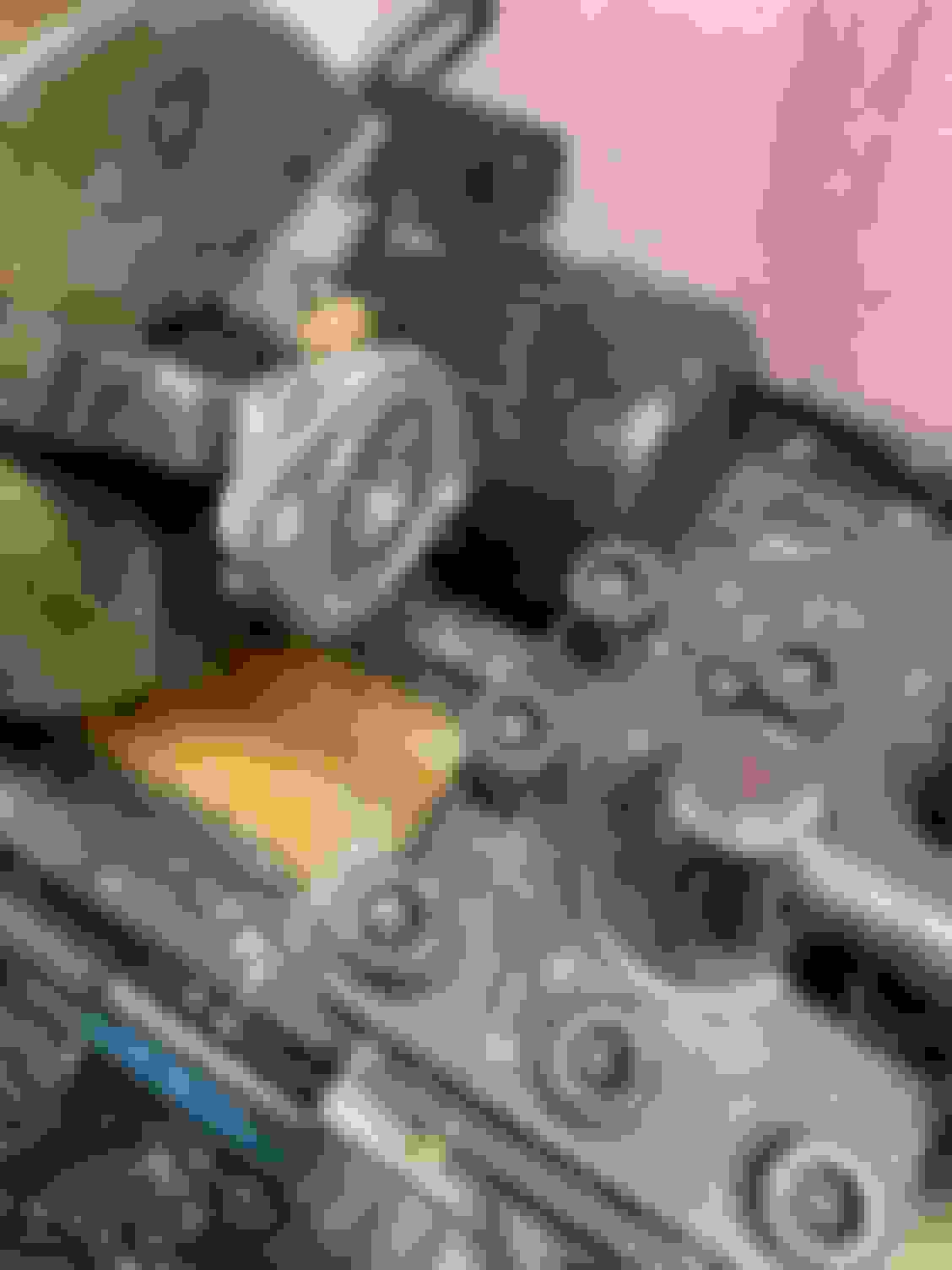
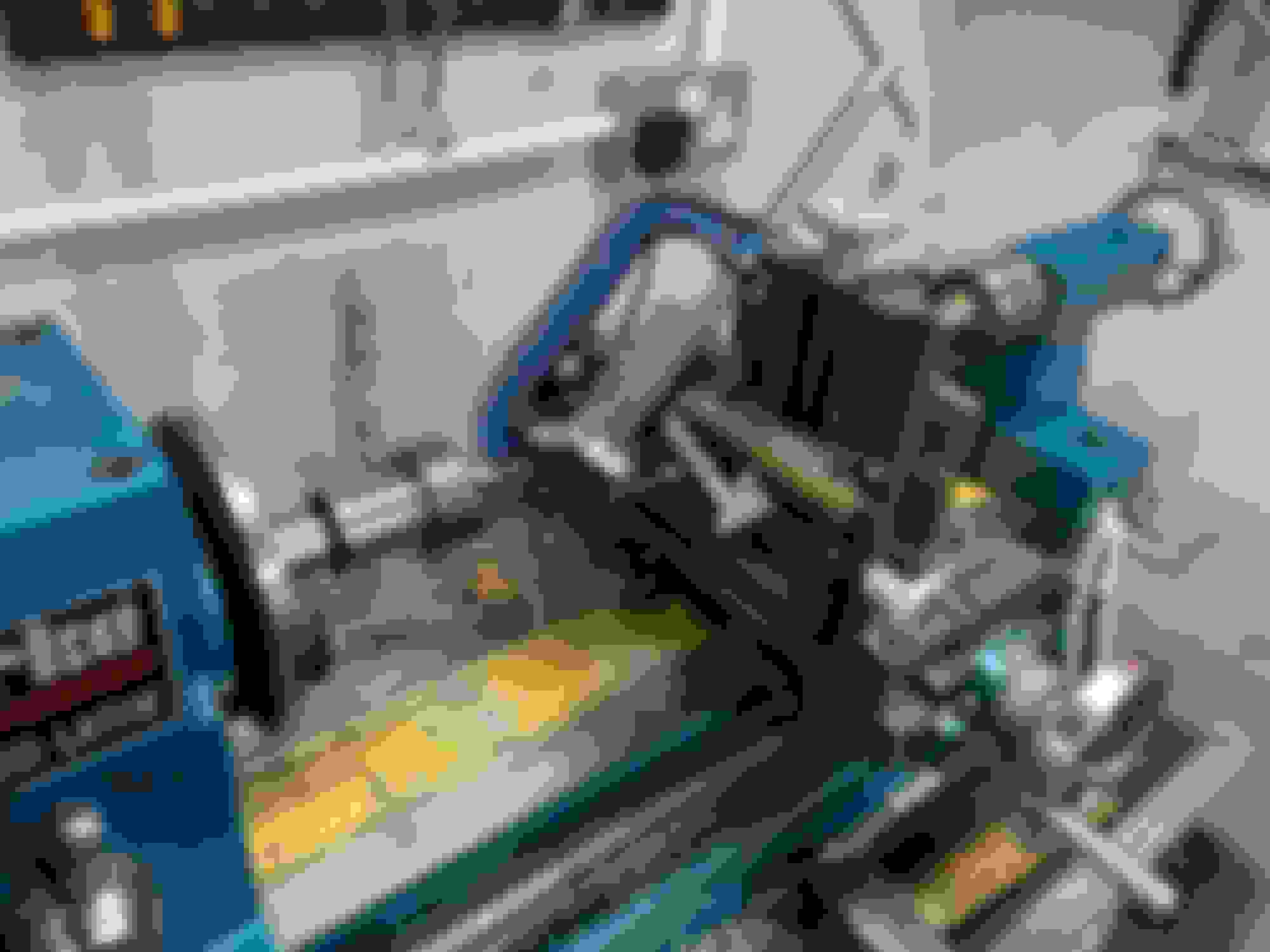
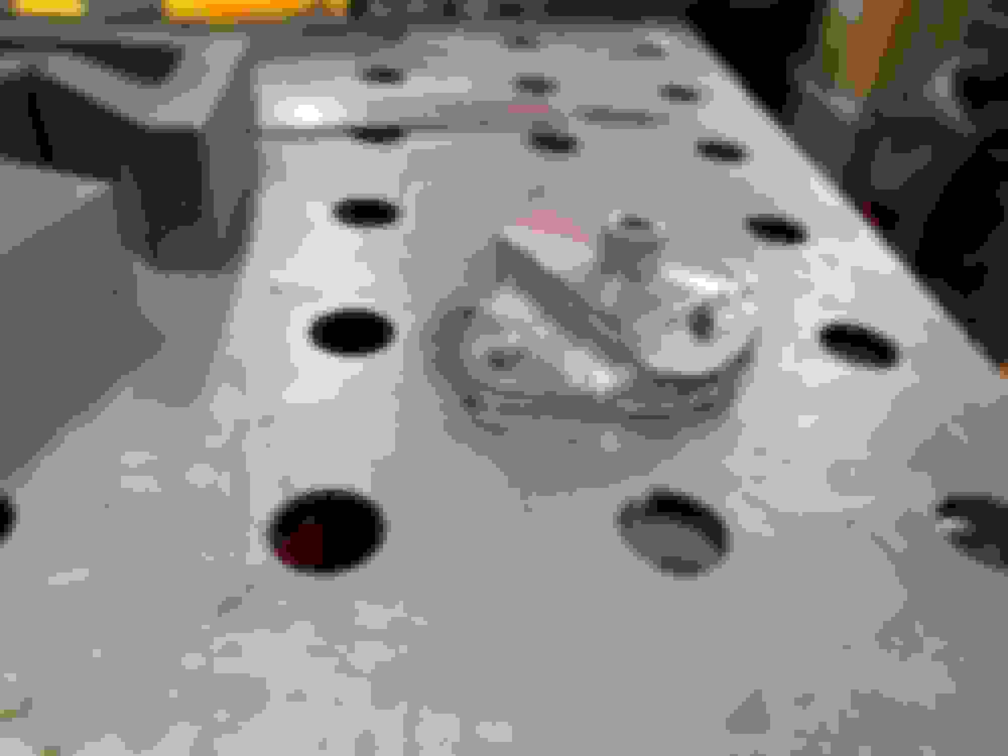
Milling a 45deg chamfer for the fitting. A proper mill is high on the list for next year. But the lathe adaption works alright for basic stuff if you accept and work within it's limitations Machined part welded to flange. Port drilled and tapped for 1/8npt -10 JIC boss welded to the part and nipple fitted
I'm generally happy with the welding. The small diameter pipework was impossible to get in a rhythm, by the time you've done two or three dabs you have to turn the pipe around or re-position, which makes it tricky to get the beads all uniform height and width. But it was a lot of good practice.
Welding on the fittings to the front plate was hard work because really it is over the capacity of my machine. I really could of done with atleast an extra 50amps, it was struggling.
Anyway, I think I am about a week away from getting the car fired up again. Hopefully it does more than look a bit mad and shiny.
I got the engine all timed up and did a leak down test. Cylinder 4 was at about 80% leak excellent.
I checked valve lash and one of the inlet valves was cracked open, which was the issue, so luckily an easy fix. Most of the inlet lashes were out and a bit over the place, all the exhaust lashes had just closed up slightly.
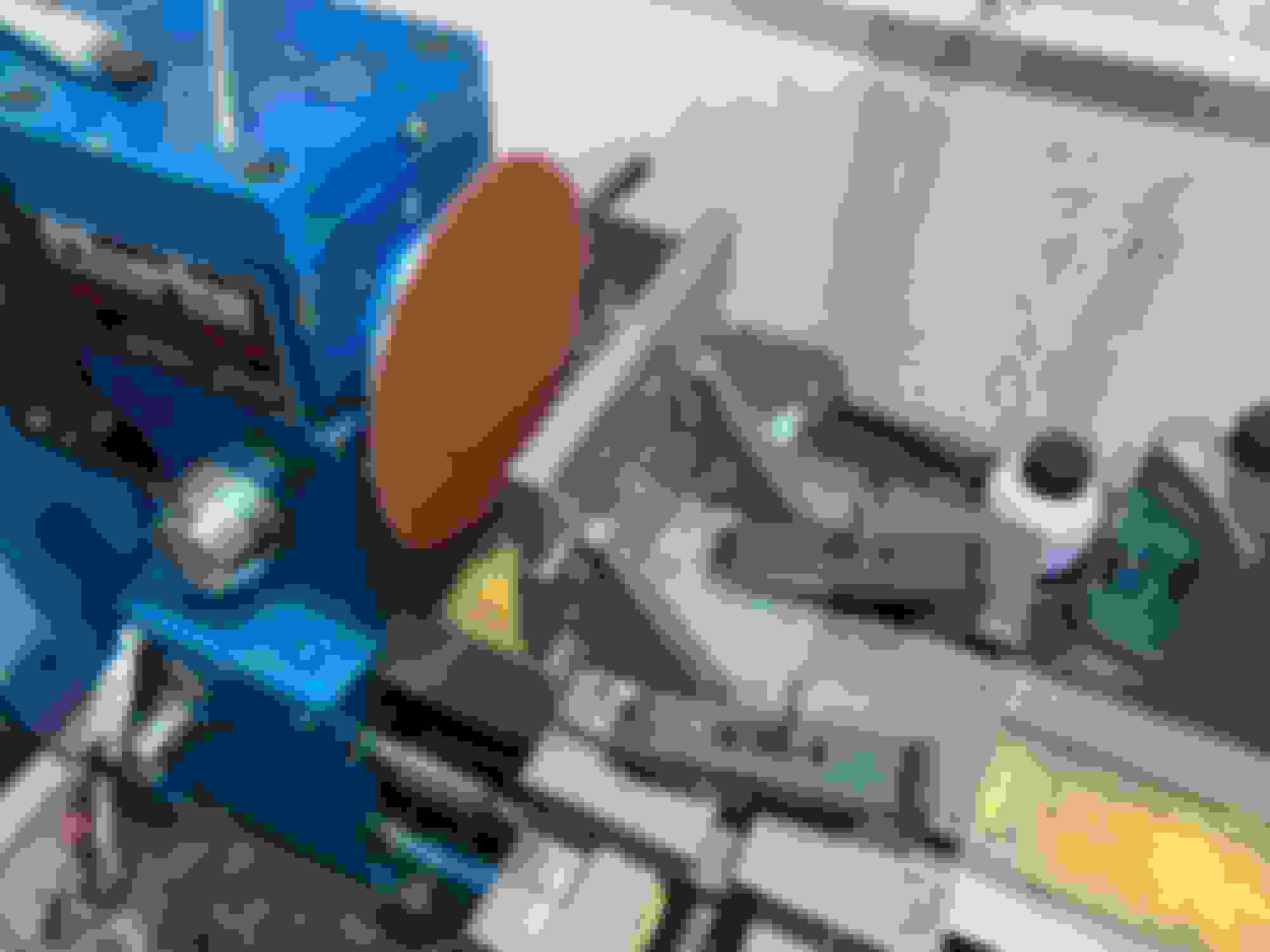
So I set up my trusty cap grinder again
Angle plate on the cross slide, and a sanding disk on the face plate. I drilled a hole in the angle plate and reamed to size to hold the little lash caps straight while grinding. Wind the carriage right next to the sanding disk and poke the cap into it with a pin or similar. Works really well and it is very controllable. If you take your time you can take height off the caps 0.01mm at a time.
Most of the inlets I was actually just able to swap around to get right, I think I had actually put them in the wrong spots in the head from when I originally ground them. The exhausts just needed 0.02-0.03mm taking off to get right.
Then I ground a HSS tool to cut an o-ring groove in the top fitting, to use the Mazda o-ring. Ground with a big relief angle to allow depth of cut without the tool dragging. Worked nicely.
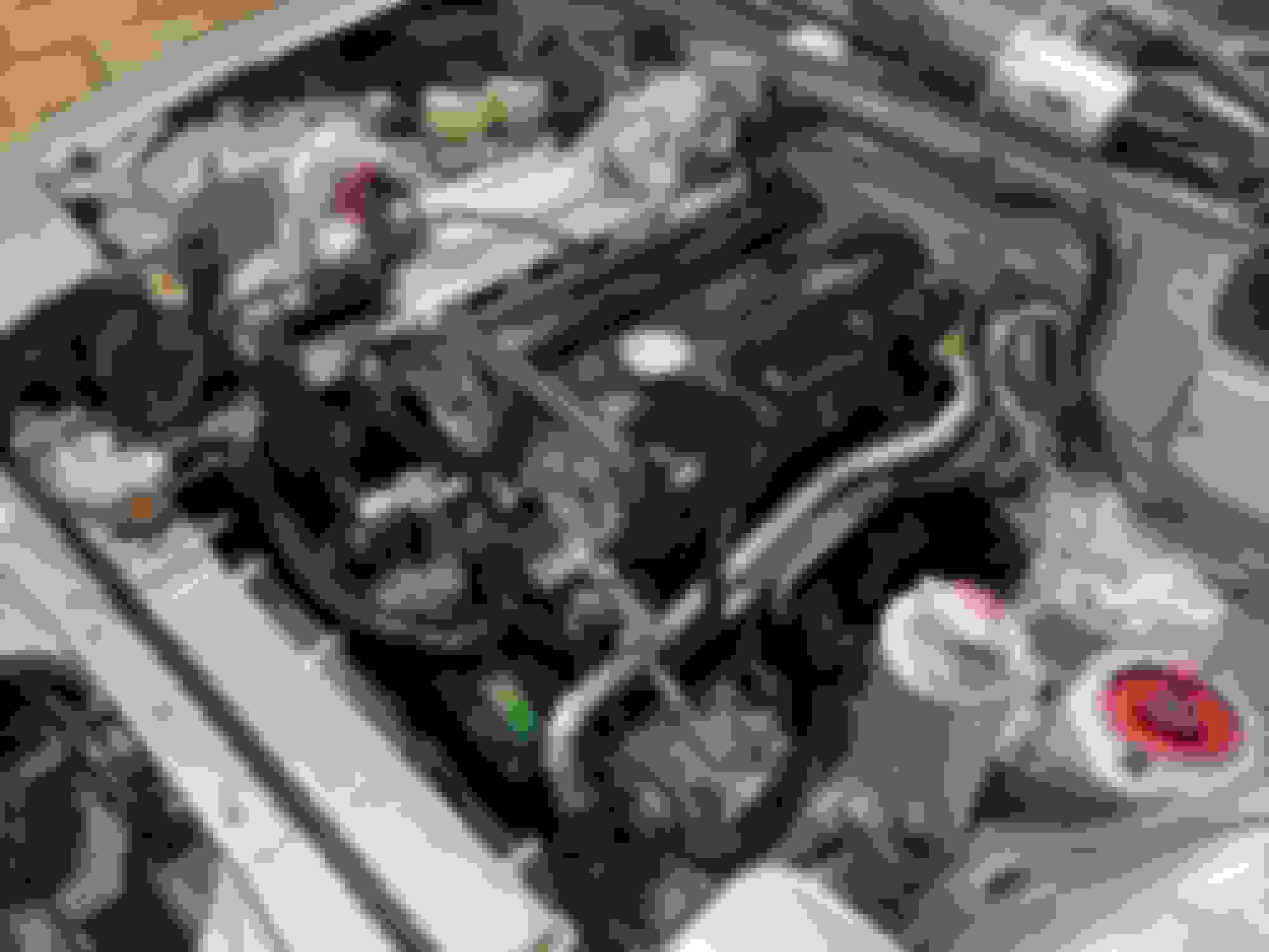
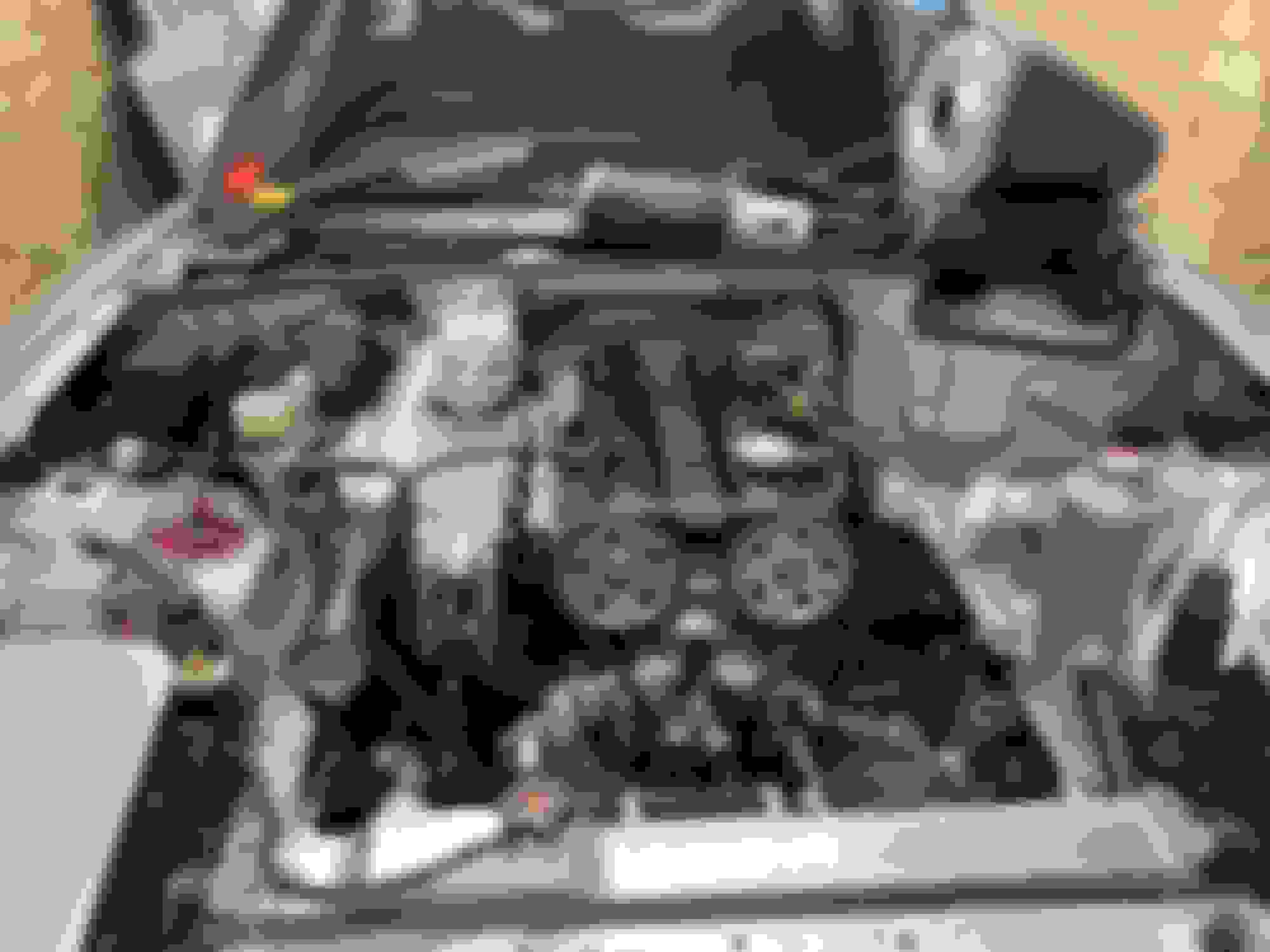
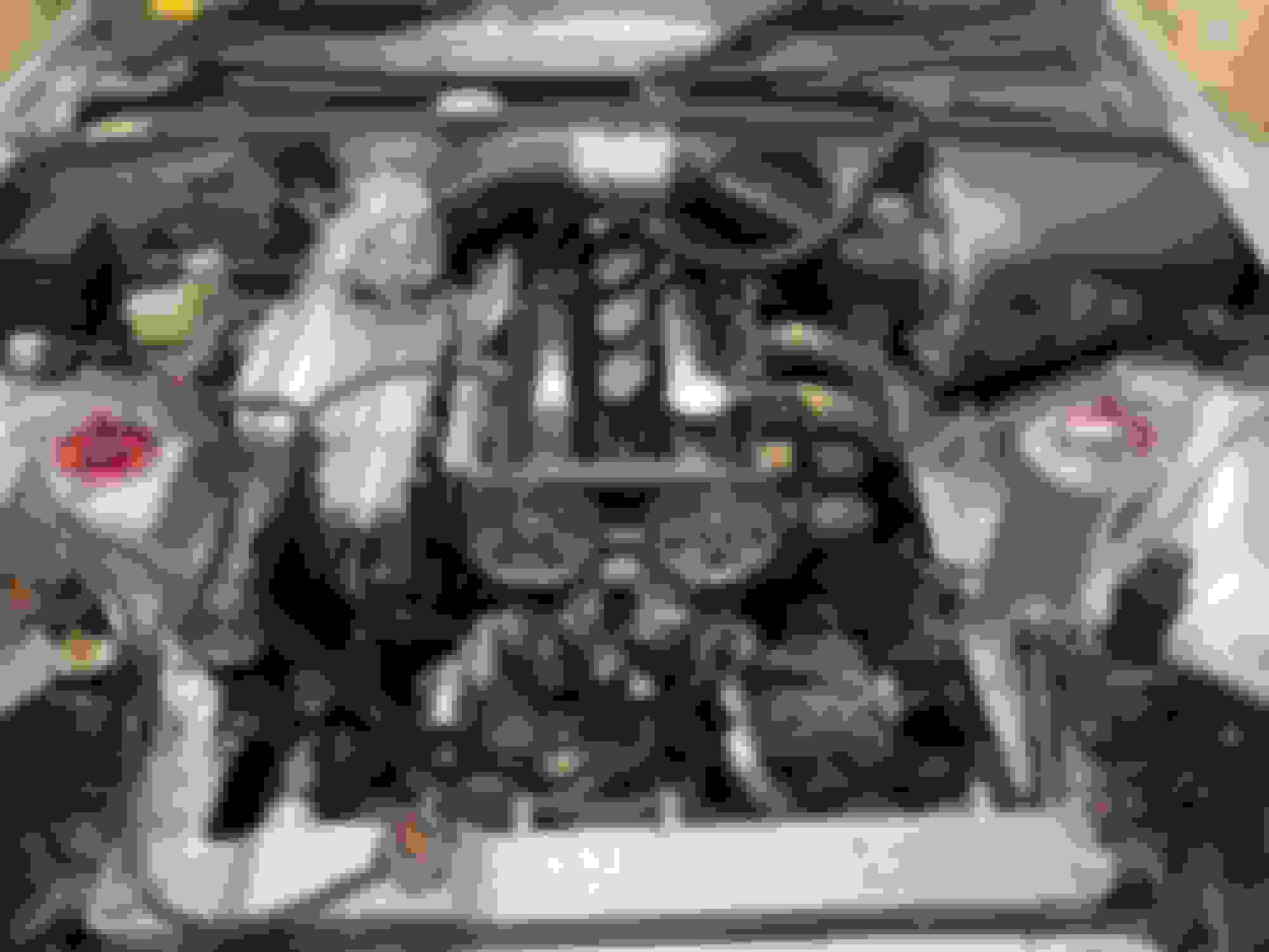
Installed on the engine. Engine all timed up again. Got the oil lines left to do, which are being a bit of a pain, final install on the coolant pipes and do the electrical install for the pump. Clean up the supercharger and chargecooler and reinstall.
Supercharger is back on the car, new cooling setup all leak checked. There was one little pin hole on the pipework, but it was easily fixed. The new layout appeared to bleed alright using the fitting on the front of the head, and the heater pipes where all full of coolant when I checked. Also the various fittings welded to the rad surprisingly well. I was expecting a bit of a struggle as the rad has been in the car for a few years with all the coolant and dirt etc, but it was fine with a good clean with acetone and a wire brush. The -16 return line wasn't as much of a pain as I thought it would be to put together and is surprisingly flexible to allow for a bit of engine movement.
Have been struggling a little with the electronics. First issue is my ECU is so packed with extra stuff it is really difficult to unpick and add new circuits etc. Also I bought the wrong type of solid state relay (for an AC current) rather than what I need (DC current). Warpspeed helped me through the issue though and in the end it was obvious, but that's normally how it goes! All the power lines etc are all run through the car. I've swapped one of my temp sensors from the chargecooler prerad to the coolant pipe to the back of the head, so I will be able to see the temp profile through the engine in logs. I also wired in an LED that will flash if either air intake temps get over 60degC (chargecooler pump failure) or engine coolant temps get too hot (EWP failure) just to give me a warning if something in those systems is up.
SSR should arrive on Monday, so will hopefully get it all fired up then. Got a trackday next weekend and will need to retune for the cylinder head and EWP so a bit short on time, and I'm on my summer deathtrap tyres still
Car is back up and running but not entirely successfully if I am being honest.
The new SSR and diode configuration for the pump got it working proportionally. Did the initial fire up and all went fine, needed a bit of dialling in but not unexpected due to the cams moving the map position of idle. Leak down tested again and all good, really happy. The new fuel system with the dead end rail seems to work too.
But the EWP setup is proving to be a real PITA. With the coolant system up to temp and pressure new pin hole leaks kept appearing. This is despite me leak checking (obviously not well enough) and being really careful to backfill the 'eyes' at the end of welds. I think I really needed to have rigged up a pressure tester for atleast 2bar.
At the moment the weather is very cold for England, -5degC to 0degC during the day. I am struggling to keep more than 50degC of coolant temp while cruising at very low pump duties. The passive heater circuit doesn't work particularly great, luke warm at best. Just about keeps the window mist free.
The other aspect is that from initial testing at low load cruise the EGT distribution (and I derive the cylinder head temp distribution from this) is worse than just with the mechanical pump and reroute.
See EGTs under cruise, top is with the EWP setup, bottom is a typical log with the mechanical pump and reroute
Cylinder 3 is a fair way out of step with the other cylinders.
So options going forward:
> Blank off half the rad and see if I can up duty cycles on the pump, to see if these evens out EGT and also generally improves running temps.
> Install the proper Davies Craig controller - this would likely bring cruise temps up better but I'd loose my pre-emptive high load cooling functionality.
> Install a thermostat on the return to the radiator. This would allow the EWP to run at higher duties and likely sort the heater issue, as the thermostat would force the coolant through it. Not sure about the EGT distribution.
The leaks are an issue on their own but I am getting very bored of spilling expensive Evans coolant on the garage floor.
I'm struggling to remember why I bothered trying this in the first place if I'm honest, particularly as the control of the pump from my ECU isn't closed loop. It will probably need monitoring as ambient conditions change. A bit of a pain. I am 75% sure I am just going to revert back to mechanical pump, and sell the EWP to recoup what I can. If it didn't leak I'd be tempted to just give it a go on the trackday this weekend, but it is a long round trip driving there and back and I'm not sure I trust it enough. If I cooked the head I'd be gutted, there's a fair bit of money in that.
This is particularly interesting (cool) work you are doing here. Props for that.
IMO, getting the thermostat back into the system will allow you to easily get back to normal operating temps and allow you to fully test what affect the pump speed has on
individual cylinder temps and maximum timing with this additional control and new cooling direction.
Having said that, from what I have read (just on the internet), the Evans coolant will not cool as well as regular coolant due it's lower specific heat capacity. waterless coolant pros and cons
Is this true or am I misguided?
Cheers Oreo,
So the lower specific heat capacity is an interesting one. It is true about the lower specific heat capacity than pure water (although I wouldn't and don't run pure water as a coolant anyway, and the mixing of glycol with the water will reduce the overall cp of a traditional coolant).
In my mind the Evans coolant will reach a slightly higher temperature than water for the same amount of energy transferred at the same flow rate. Equally on the radiator side less energy needs to be transferred out of the Evans for it to be cooled to a given temperature.
The slight increase of end temperature of the coolant in the engine block will result in slightly less heat transfer owing to the slightly lower logarithmic mean temperature difference, but then that increase in entry temperature to the radiator helps the LMTD on the radiator side of the equation.
So I think it doesn't matter massively, although I can't say I've worked it out mathematically.
The driver to use the Evans was the fear of steam pockets forming in the head around the exhaust ports. The massively higher boiling temperature over a traditional coolant at low pressure should avoid this. I didn't want to even try using a normal coolant, because if I did have an issue I would only know by having a major mechanical issue, on an expensive engine.
I took the car for a second drive and did two things - blocked half the radiator, realised the ramp up in the pump map was too aggressive and backed out the duty a bit.
This combo realised a running temp at the exit of the block of about 72-75degC - a little cool but there is still room to back the pump out a bit in the ramp up. Also at this temperature the heater function has returned and is totally acceptable. It's no furnace but absolutely fine, even in what is very cold weather.
I would be interested to see what happens if I remove the radiator blockage and just use the lower pump duty, as it did seem to be the pump duty adjustment that I made halfway through the drive that made the big difference to running temp.
Also with these mods cyl3 seemed to stay more in tune with cyl4, within about 10degC give or take. Cyl 1 and 2 as a pair run colder than 3 and 4. I think this means that if I put a restrictor in the front feed I could potentially even out the two pairs of cylinders, back to where I started with the reroute
The old temp distribution was interesting cyl1 and 2 used to dance around each other being the coldest on cruise then cyl 3 then cyl 4 being the hottest. On the power cyl 1 ran coolest (I think due to running richer than 2, due to the intake manifold geometry having only really 3/4 of a proper radiused entry to the port) 2 and 3 ran the hottest (I think because they ran slightly leaner as they had the prime position in the manifold) then 4 between 1 and (2,3), because it ran similarly rich to cyl 1 owing to effectively the same geo issue, but it got the hotter coolant.
On the leaks I am going to pull off the pipework and front plate. Use some silicone behind the pump plate as well as the gasket, and get the JB weld on the pipework. At this point the pride is in the bin - I would just like to give it a fair go and dyno tested (although it will be with the new head so unfortunately not a true back to back) which will be happening early Jan. I'll make a decision after that if I keep it or revert back to the mechanical pump. It just feels like a bit of a faff at the moment, albeit an interesting faff.
Car is back up and running but not entirely successfully if I am being honest.
The new SSR and diode configuration for the pump got it working proportionally. Did the initial fire up and all went fine, needed a bit of dialling in but not unexpected due to the cams moving the map position of idle. Leak down tested again and all good, really happy. The new fuel system with the dead end rail seems to work too.
But the EWP setup is proving to be a real PITA. With the coolant system up to temp and pressure new pin hole leaks kept appearing. This is despite me leak checking (obviously not well enough) and being really careful to backfill the 'eyes' at the end of welds. I think I really needed to have rigged up a pressure tester for atleast 2bar.
This past summer I switched to the Davies Craig EWP150, after the Pierburg CWA200 failed (and aftermarket CWA replacements failed to control flow via PWM correctly/at all). It's a loud unit that seems pretty obvious it's running (or not). I too am controlling it via a new SSR (the CWA has this built in), but no extra diode. Not sure what you mean by that. The LED to tell you temps are wrong? I run a thermostat and haven't noticed coolant temp issues with either EWP's.
I was going thru your posts just now and saw all the welded aluminum coolant pipes, and immediately though "**** that and the pinholes it creates". yeah it's a bitch, sorry to see you're dealing with that. I'm not ashamed to admit, some of my pinholes have been plugged successfully by jbweld putty.
Do you just turn the pump on and run it 100%, and let the thermostat regulate the temp Tim? The diode is to manage the inductive loads generated when you cut the current to the motor and it's electromagnetic fields collapse. It can be a very significant voltage spike that needs to be managed. The diode provides a circuit for this energy to dissipate even with the SSR open. This is important for me because I am switching the pump on and off at 30Hz, that's a lot of potentially harmful energy that needs managing. If you are running the pump 100% you will only generate that energy when you turn the car off, so nowhere near the same frequency.
Ha ha yes rod for my own back. I knew it was something to be careful of, thought I had been meticulous enough and been proved wrong. There's only a couple of tiny leaks to find now, but it does my head in.
Do you just turn the pump on and run it 100%, and let the thermostat regulate the temp Tim? The diode is to manage the inductive loads generated when you cut the current to the motor and it's electromagnetic fields collapse. It can be a very significant voltage spike that needs to be managed. The diode provides a circuit for this energy to dissipate even with the SSR open. This is important for me because I am switching the pump on and off at 30Hz, that's a lot of potentially harmful energy that needs managing. If you are running the pump 100% you will only generate that energy when you turn the car off, so nowhere near the same frequency.
Hmmm yes. I believe I have messed that circuit up. I am running mine at around 30Hz as well I believe. I doubt my SSR is inductive rated. What diode are you using?
EDIT: I'm thinking something like a 15SQ045 Schottky style diode would be good, but I'm no electronics person.
Hmmm yes. I believe I have messed that circuit up. I am running mine at around 30Hz as well I believe. I doubt my SSR is inductive rated. What diode are you using?
I have seen some SSRs have a built in 'snubber' which is a similar protective device, although not exactly the same as it won't be across the terminals of the motor
The diode I am using is an 650V 30A TO-247-2L UF Recovery Diode
I have seen some SSRs have a built in 'snubber' which is a similar protective device, although not exactly the same as it won't be across the terminals of the motor
The diode I am using is an 650V 30A TO-247-2L UF Recovery Diode
I'm thinking something like a 15SQ045 Schottky style diode would be good, but I'm no electronics person.
I'm thinking something like a 15SQ045 Schottky style diode would be good, but I'm no electronics person.
Similarly neither am I. For my WI system and settled on a 30A rated diode very similar specs to the one I am using here. That was simply based off of the running current x safety factor (3), but the actual maths and experimentation needed to properly calculate is more complex. The WI pump a little less hungry on juice than the EWP I think but they are both in the same ballpark up to 10A.
And you can spec diodes to manipulate the inductance in different ways. On a fuel injector or the driver for my WI solenoid the FET has a clamping voltage diode inbuilt - this lets the induced voltage build to a higher set point before being tapped off, dissipating the energy quicker and closing the injector / solenoid quicker to achieve better modulation of whatever medium it is controlling. And with motors you can do the opposite, spec a diode to allow the induced current to recirculate and only slowly bleed the energy off, allowing the motor to run on to smooth the otherwise harsh input signal. My understanding is the diode through varying levels of backward resistances converts the induced current into heat energy.
Take the above with a pinch of salt, but that is my knuckledragger understanding of managing inductance in circuits like this.
Last night I installed a restrictor in the front feed, 6mm diameter down from the natural 12.5mm hole previously, and glued the area I thought was leaking.
I took the car for a test run at lunch, without the rad blocked off, with the less aggressive pump ramp.
Results were the same as previously. The car didn't get up to temperature on the move, heater was cool, cyl 3 hotter than the rest.
Also when I let the car idle on the driveway, simulating waiting for a run, I didn't actually have any additional control of engine temperature by ramping up the pump duty cycle. The weakness is the radiator / fan setup seemingly not the flow rate, which was interesting, but also another nail in the coffin.
The pipework didn't leak this time though, I got the last of it I think.
But bearing in mind the current headwinds I can't be fussed with it anymore. I am going back to the mechanical pump with a reroute.
With a thermostat I think it would work heaps better, I'm sure the heater would work properly and getting up to temp wouldn't be the chore it currently is.
I don't seem to be able to manage stationary temperatures as well as I thought I would be able to.
The temp distribution is currently worse than I saw with the mech pump and re route.
I have water injection, which is still not dyno tested to make up for any short comings in fuel octane to make MBT.
As much as I don't like shelving stuff, I'm struggling to see the gold at the end of the rainbow on this one, and I have other things I need to be cracking on with.
I'm going to get it switched back over Christmas ready for the dyno testing of the new cylinder head, and do some proper dyno testing of the water injection.
So I took a look at integrating a thermostat into the front plate, but at 50mm diameter it is too big to fit with the heater take off and temp sensor. Moving it onto the neck before the AN fitting would push the AN fitting too far forward into the fan / rad. I probably could do something with a complete remake of the front plate and some imagination but I'm kind of over it.
I then thought about giving the Davies Craig controller a go, to see if its management strategy could solve the heating issue. At first it does a 6v pulse on and off for 10seconds, then waits 30seconds. Then as you get closer to target temp it pulses for 10 seconds then off for 10seconds, then just below temp ramps without any off time. The controller uses it's own standalone temperature sensor that needs to be installed. I drilled and tapped a hole in the front plate but unfortunately the limitations in places I could actually drill overlapped with the room the cambelt tensioner needs to move. I had left this area clear on purpose previously and it proved why. I can't really get it on the neck before the AN fitting because it would either be in the cambelt or interfering with lines. So no particularly easy solution I like for this.
And, to be honest, I'm not really annoyed about it all. Just one of those things. I'm looking forward to reverting back to my simple reliable fuss free reroute setup. I would have liked to have seen the delta hp but it also wouldn't have been a fair test anyway. I have the bigger cams, porting, valves and more compression now. If I did see a power difference I wouldn't have known how much came from what anyway.
I'm going to shelve the idea for now but maybe revisit it on a simpler cheaper engine with the aim of back to back testing it.
Anyways, have a great Christmas and New Year, I will pick this back up with the dyno testing in January.
Some updates from initial tuning of the cylinder head which are quite interesting / encouraging.
5000rpm:
Overlay of a pull from today and my dyno session about this time last year, with a stock BP4W head.
It's quite interesting. The new head is running a higher MAP here, which I'm not surprised about as I know that with these cams the boost curve is flattened, i.e it makes pretty much constant boost through the rev range whereas boost increases as revs climb with the stock BP4W head. But for the same AFR it needs a whole lot more fuel, see the PW values, the new head needs 11% more pulsewidth. I find it a bit odd that the head at this rpm makes more boost (restriction) but is then calling for more fuel (indicating a higher mass air flow, the important bit). I would expect a drop in boost to accompany an increase in fuel requirement. I've checked the tune and there isn't any difference in injector values like dead time etc, voltages are all consistent.
The barometric pressure is higher today at around 101kPa. The dyno test day was around 98kPa (and at that time the sensor was hooked up to the intake tract, testing vacuum so its not baro during the pull). This will explain a fair bit of the boost pressure increase, and probably a bit of the pulsewidth. Will be interesting to see on the dyno with corrected figures.
7000rpm:
This is really where the new head is running away with it. Lower boost (despite higher baro pressure), higher pulsewidth and running a lot leaner (0.8afr).
I took the car up to 7600rpm and the duty on the injectors is up to 85% and I could do with adding more fuel to get afrs down to 11.5 or there abouts. It revs happily up there. It was very slippery out so to be honest I was concentrating on not binning it but hopefully the top end urgency I missed has returned.
My thoughts are maybe advancing the intake cam a little more will yield more midrange efficiency at no real expense to the very top end, so will try that out on the dyno, should be pretty easy to tell by looking at the fuelling and torque figures if it is doing anything.
Another interesting point in the data is that the EGT distribution has remained the same as it was with the EWP, so the worse distribution is a result of my handiwork on the head rather that the cooling system. Shows how sensitive the ports are as my intake work was not massively intrusive, but I did not test on a flow bench.
Woo hoo dyno results are in! Day didn't start off well as I spilt a coffee under my passenger seat so the car now smells of increasingly stale milk, but the bad luck did not continue.
We got the tyres warmed up and let her rip on the tune I'd put in and straight away we were up at 300whp. We played with the ignition timing a bit and got multiple runs all in the 310whp / 350bhp / 260lbft range. The recipe of mild port, biggish cams, +1exhaust valve, a fair amount of exhaust port work, compression and a bit of rpm appears to have worked. This is at the same dyno as last time, same pulleys on the supercharger.
We moved the cams about but I was very pleased that the best settings were the advanced intake cam and straight up 102/110 settings I'd found on the road, but to be honest there wasn't masses of power between settings, 2-5bhp max really. Advancing the exhaust further lost a little power, which was interesting as that direction decreases overlap, and increases blow down time. Retarding the exhaust cam gave the same power figures as the straight up position, so I think the exhaust flow is nicely matched to the application. I am running quite a high overlap setup, 50-60deg 'seat to seat' by the time the lash is taken up.
We then tested the stock BP4W intake cam. If you remember from my simulations way back, this cam looked to be the sensible choice, a boost in peak torque and not much trade in the top end. But on the dyno we couldn't get the car to make more than 290whp / 250lbft. The whole rev range required fuel to be pulled out the map to get back into the mid 11s, and when compared against the power curve of the big intake cam it lost out over the whole rev range which was very interesting. The bolder trace below is the stock intake cam pull, the faded trace the big intake cam. The difference is subtle but you can clearly see fuel requirements are higher, boost lower and the run quicker with the big intake cam.
The increased compression ratio showed its teeth a little 3500rpm and under, where I needed to full quite a few degrees out the tune to avoid pinging, so I think actual 9.5:1CR with normal petrol on my setup is about optimum, I'm not going to go and shove another point in it and start compromising timing higher up the rev range where I actually use it.
Here is a run comparison comparing the best stock head dyno run (when I fitted the current big filter hanging out the engine bay) from last year (faded line) with the new head big cam setup. I checked the barometer and both runs were done at 98kPa. Again, fuel requirement way higher, boost pressure lower basically everywhere, and the pull is quicker. Last years best run on this dyno, big filter and a sprinkle of spark advance.
We also tested the water injection for power this time, which was very educational. Just switching the WI on with the same fuel and advance lost power everywhere, even in the top half of the rev range where I can achieve 15-20% water to fuel. We leaned the fuel out to around 12.5AFR and added a couple of degrees timing and we regained the non WI power from 5000rpm +. We added another degree but it didn't show a particular response so we put it back and left it.
Where I do have work to do is in the sub 5krpm area. The minimum amount of water I can reliably flow is about 260ccmin. Below this the nozzles sort of just spit rather than nicely atomise. The issue is that at 3500rpm this equates to about a 30% water to fuel, tapering back to 20% by 5k. The effect of this is below:
So I think I am going to try a smaller restrictor in the line before the PWM valve to see if I can pull down that minimum flow rate. The other option is to only switch the water on at 5krpm, but it takes a few fractions of a second to respond, so I quite like to 'get it off the seat' early on in a pull.
Not all gloom though - the WI made peak torque 500rpm earlier with the extra timing lower down, so I think if I can tame the early stage WI I can extend the torque band lower safely.
Something to fiddle with anyway, there is certainly on track performance available there, as I often use the low end to pull me out a corner rather than have to faff around with another gear change before the exit curb.
Last edited by Tchaps; 01-12-2023 at 03:58 PM.
Reason: Mo graphs
This is where I started with the slower pulleys and interestingly the same cams I am using now:
Then came the 2hp power pulleys a month or so later:
Then there was a bit of a break, I crashed it, rebuilt it, added WI and the big bore exhaust, then I blew up the piston skirts with a dodgy vacuum connection and did in my cammed cylinder head with a dremel.
I tested the new engine, with a stock BP4W head at a different more local dyno, which gave me sad numbers. Looking back I don't know if it was the rings not being broken in from my not exactly faultless launch of the new engine, whether it was a setup error on the dyno or if it is just a lower reading dyno. This graph was the run that I just had a velocity stack on the throttle body, which gave +10hp over the filter / airbox setup at that time.
So I took it back to the original dyno a month or so later after using the Morris magic oil and it made the same power as last time on that dyno, just with a lower compression ratio and the stock BP4W. Then with the new larger less restrictive filter and a bit of spark advance we cracked 300bhp at the crank.
Built the carbon airbox and ragged it around for a year, half of it burning oil from some dodgy valve seals to now installing the new cylinder head. 264/264 advertised duration 10mm lift. 102/110deg at max lift. Supertech single springs, SUBs (can't remember what brand I've had them ages). Standard size but back cut and waisted Supertech intake valves with bowl work and 3 angle seats. Deshrouded and equalised chambers skimmed for 9.5:1CR. +1 exhaust valves (Supertech again) fairly extensive remodelling of the exhaust port.
So from installing the current pulleys back in August 2020 power / torque has gone from 255whp / 285bhp / 230lbft to 310whp / 350bhp / 265lbft or +55whp / +65bhp / +30-35lbft

 11-27-2022, 05:05 PM


 2
2


 excellent.