
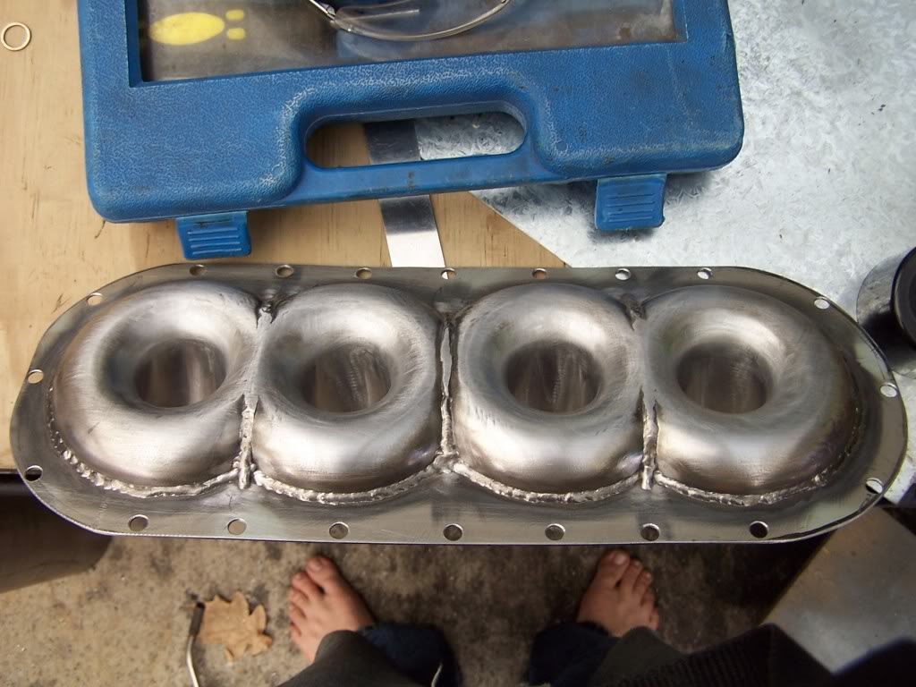
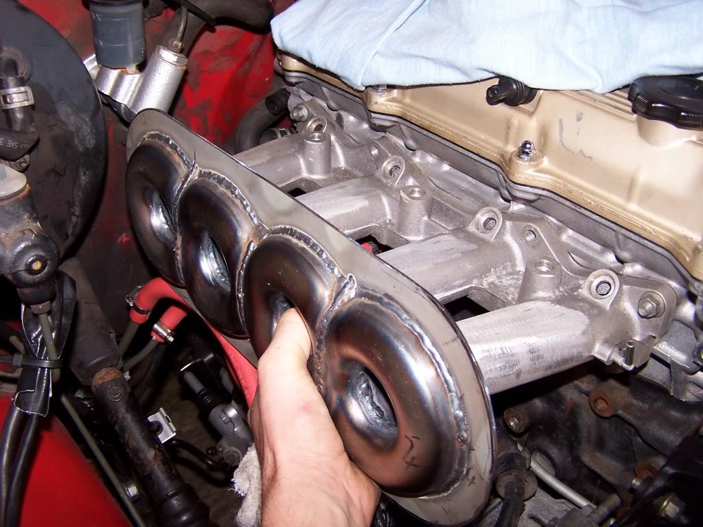
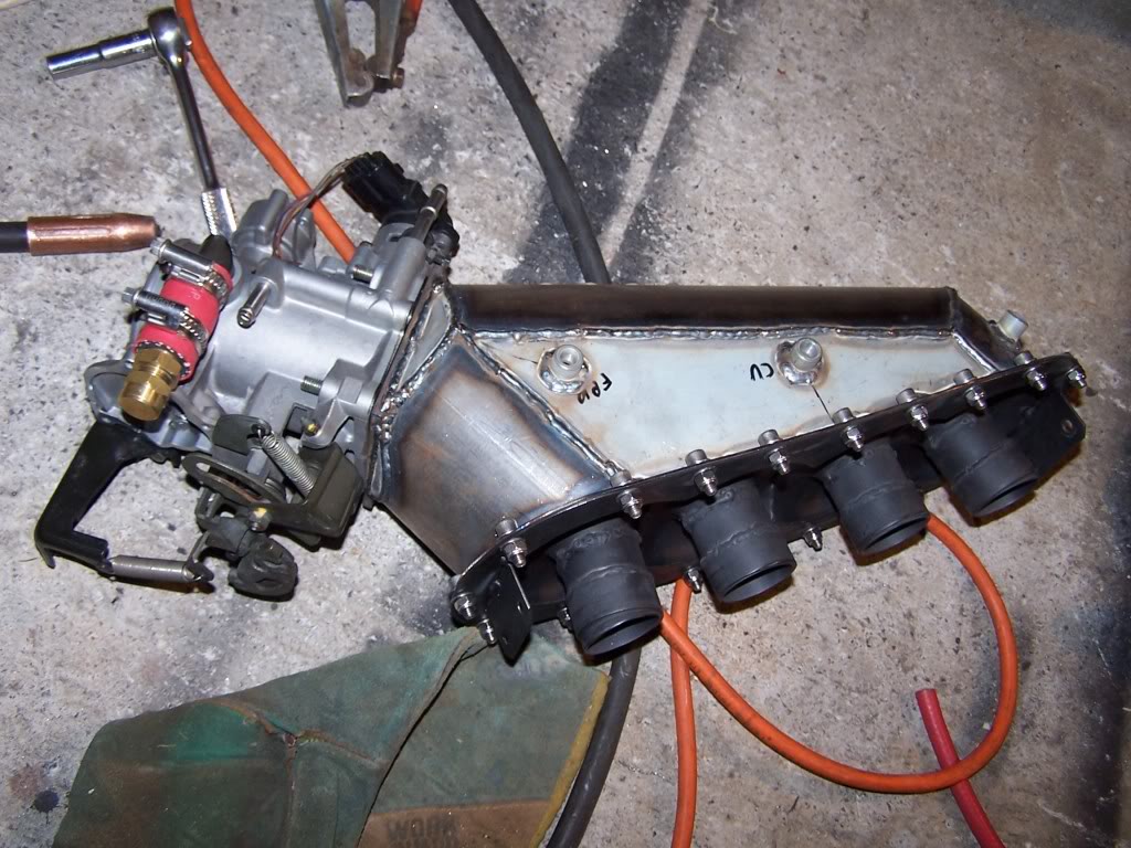
Begi Intake Manifold


The only thing I really found suggesting a raised velocity stack was when the stack inlet radius was toroidal (meaning, not a constant radius). For a constant radius inlet, the stack was suggested to be flush against the floor.

Reply
 0
0

0


Former Vendor
Joined: Jun 2006
Posts: 1,337
Total Cats: -100
From: Bell Tuning & Performance
Reply
0
0
Former Vendor
Joined: Jun 2006
Posts: 1,337
Total Cats: -100
From: Bell Tuning & Performance
Stephanie
Reply
0
0


I was playing some more.
I really like the idea of a tapered IM. With what I'm finding, it's providing the best flow into #4. A little too good in this certain case:

I removed the stacks...seems like they really helped create a larger area to pull airflow from. With the stacks back in place I got flow back into #1.

so then I thought, why not move the TB inlet back 2" inches to see what difference it had...in the same conditions it flow like the first one...it's almost like the stack of #1 needs to be right at the inlet to work.

so at this point I thought angling the TB would be the best to retain that lost flow but as to not disturb the airflow to the rear of the manifold. Which seemed to help.

I was really starting to like this shape, so I went crazy with teh inlet and did the common "teardrop" shape and saw pretty good results.

I really like the idea of a tapered IM. With what I'm finding, it's providing the best flow into #4. A little too good in this certain case:
I removed the stacks...seems like they really helped create a larger area to pull airflow from. With the stacks back in place I got flow back into #1.
so then I thought, why not move the TB inlet back 2" inches to see what difference it had...in the same conditions it flow like the first one...it's almost like the stack of #1 needs to be right at the inlet to work.
so at this point I thought angling the TB would be the best to retain that lost flow but as to not disturb the airflow to the rear of the manifold. Which seemed to help.
I was really starting to like this shape, so I went crazy with teh inlet and did the common "teardrop" shape and saw pretty good results.
Reply
0
0

Joined: Jun 2005
Posts: 19,338
Total Cats: 574
From: Fake Virginia
scott, humor me here. use this model and add a tiny ridge around the inside edge of the inlet tube about half way in. like a pipe bead but on the inside. maybe .06 high. then re-do this simulation.
Reply
0
0
You can see I tried that between images 2 and 3.
The differences between all the above are
1. no stacks.
2. stacks
3. 1.3" added between wall and stacks
4. 14� angle on inlet.
5. crazy angled inlet and teardrop taper.
I mean hell knows if I'm setting up these pressure boundaries correctly, but it's pretty obvious which variation flows evenly the best. This has me thinking about something, going to try a different inlet variant.
Reply
0
0
Joined: Jun 2005
Posts: 19,338
Total Cats: 574
From: Fake Virginia
You can see I tried that between images 2 and 3.
The differences between all the above are
1. no stacks.
2. stacks
3. 1.3" added between wall and stacks
4. 14� angle on inlet.
5. crazy angled inlet and teardrop taper.
I mean hell knows if I'm setting up these pressure boundaries correctly, but it's pretty obvious which variation flows evenly the best. This has me thinking about something, going to try a different inlet variant.
The differences between all the above are
1. no stacks.
2. stacks
3. 1.3" added between wall and stacks
4. 14� angle on inlet.
5. crazy angled inlet and teardrop taper.
I mean hell knows if I'm setting up these pressure boundaries correctly, but it's pretty obvious which variation flows evenly the best. This has me thinking about something, going to try a different inlet variant.
Reply
0
0


