
My awesome daily project 35mpg/150whp highway donut

Thread Starter
Joined: Jun 2006
Posts: 29,085
Total Cats: 375
From: Republic of Dallas
I appreciate the help, but I'm not an electrical engineer so I have no idea what I'm doing. All I know is I have a sync-loss problem and nothing more.
Reply
 0
0

0
Thread Starter
Joined: Jun 2006
Posts: 29,085
Total Cats: 375
From: Republic of Dallas
Should I call DIY and ask about this or am I barred from support due to not using MSpnp2? I'm about to get some help from someone on here with the soldering and if things go wrong and this is like a bad joke or something, I'm in trouble.
Reply
0
0
1) Remove the two resistors mentioned (R2 and R3)
2) Desolder white wire from pin 1 and solder it on white wire on pin 3
3) Desolder pink wire from pin 2 and solder it on pink wire on pin 4
4) Enjoy your car
2) Desolder white wire from pin 1 and solder it on white wire on pin 3
3) Desolder pink wire from pin 2 and solder it on pink wire on pin 4
4) Enjoy your car
Reply
0
0
Thread Starter
Joined: Jun 2006
Posts: 29,085
Total Cats: 375
From: Republic of Dallas
Reply
0
0

Junior Member

Joined: Apr 2011
Posts: 83
Total Cats: 3
Pre:
Post:
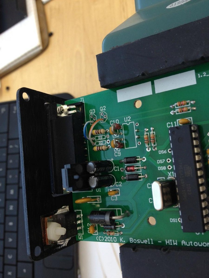
As you can see, R2 and R3 are already gone from the pre-mod, and Q2 and Q3 are gone from post-mod.
Also, I see no wires in the pre-mod picture that need to be desoldered, as mentioned in steps 2 and 3.
And frankly, I don't know where you are getting the pin number references.
Looks like the connection from one of the pins on the DB9 connector that goes to R2 is being taken to Q2, but since I'm guessing this is at least a double layer PCB, I can't follow all the traces.
Any further clarification would be appreciated, as I don't want Hustleberry crying if something adverse happens

Reply
0
0

Reply
0
0
Thread Starter
Joined: Jun 2006
Posts: 29,085
Total Cats: 375
From: Republic of Dallas
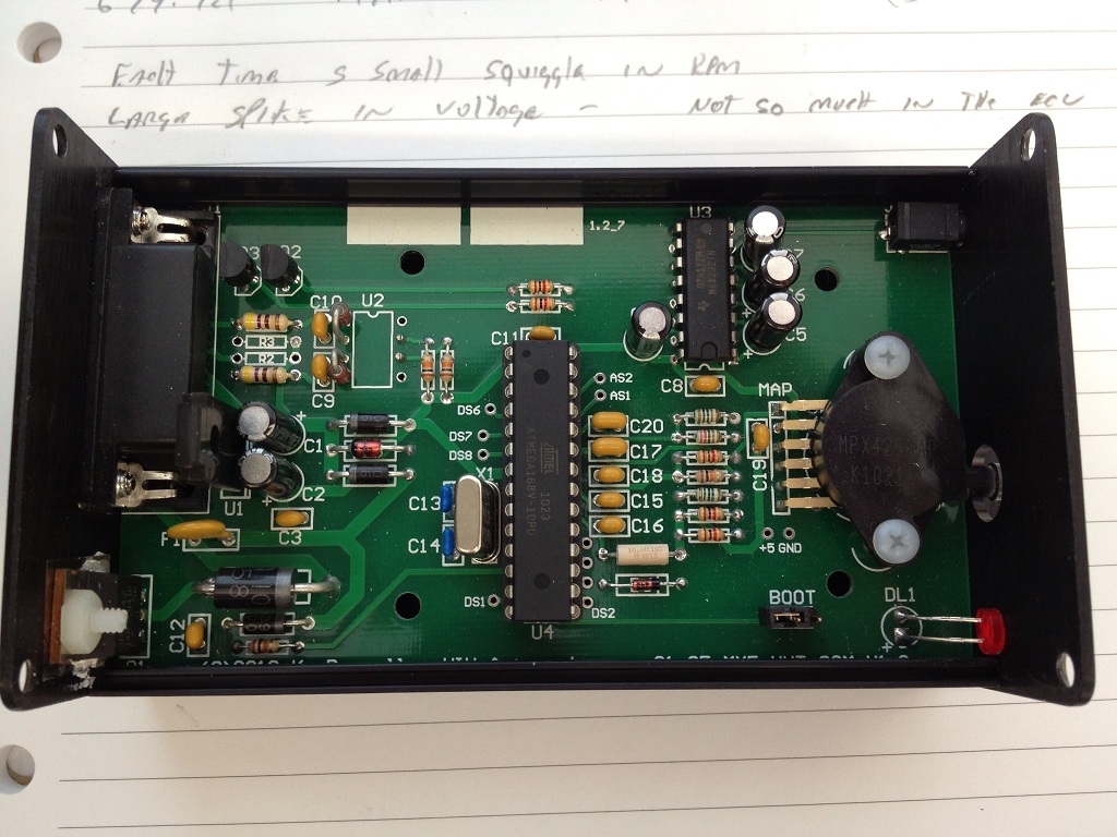
I have two photos, one is supposedly pre-modification and the other post-modification
Pre:

Post:

As you can see, R2 and R3 are already gone from the pre-mod, and Q2 and Q3 are gone from post-mod.
Also, I see no wires in the pre-mod picture that need to be desoldered, as mentioned in steps 2 and 3.
And frankly, I don't know where you are getting the pin number references.
Looks like the connection from one of the pins on the DB9 connector that goes to R2 is being taken to Q2, but since I'm guessing this is at least a double layer PCB, I can't follow all the traces.
Any further clarification would be appreciated, as I don't want Hustleberry crying if something adverse happens
Pre:
Post:
As you can see, R2 and R3 are already gone from the pre-mod, and Q2 and Q3 are gone from post-mod.
Also, I see no wires in the pre-mod picture that need to be desoldered, as mentioned in steps 2 and 3.
And frankly, I don't know where you are getting the pin number references.
Looks like the connection from one of the pins on the DB9 connector that goes to R2 is being taken to Q2, but since I'm guessing this is at least a double layer PCB, I can't follow all the traces.
Any further clarification would be appreciated, as I don't want Hustleberry crying if something adverse happens
Reply
0
0
Junior Member
Joined: Apr 2011
Posts: 83
Total Cats: 3
I'm getting conflicting information that doesn't correspond with pictures and without a proper VVTuner PCB schematic, I'm a little in the dark.
Reply
0
0


Thread Starter
Joined: Jun 2006
Posts: 29,085
Total Cats: 375
From: Republic of Dallas
Reply
0
0
Junior Member
Joined: Apr 2011
Posts: 83
Total Cats: 3
Reply
0
0
Do exactly as I said. Exactly.
If R2 and R3 are already removed, obviously omit that step.
If you look closely at the DB15 connector, the pins are labelled.
Looking at the connector on the VVTuner, pin #1 is on the top left. It has a white wire on it. Remove it from #1 and solder it on pin #3, which is also a white wire.
Do the same with the pink wire on pin #2. Remove it and solder it on #4.
Simple as that.
Ignore any other information you have seen, heard.
Reply
0
0
Junior Member
Joined: Apr 2011
Posts: 83
Total Cats: 3
Do exactly as I said. Exactly.
If R2 and R3 are already removed, obviously omit that step.
If you look closely at the DB15 connector, the pins are labelled.
Looking at the connector on the VVTuner, pin #1 is on the top left. It has a white wire on it. Remove it from #1 and solder it on pin #3, which is also a white wire.
Do the same with the pink wire on pin #2. Remove it and solder it on #4.
Simple as that.
Ignore any other information you have seen, heard.
If R2 and R3 are already removed, obviously omit that step.
If you look closely at the DB15 connector, the pins are labelled.
Looking at the connector on the VVTuner, pin #1 is on the top left. It has a white wire on it. Remove it from #1 and solder it on pin #3, which is also a white wire.
Do the same with the pink wire on pin #2. Remove it and solder it on #4.
Simple as that.
Ignore any other information you have seen, heard.
That's really helpful
Reply
0
0


