
My awesome daily project 35mpg/150whp highway donut


Cylinders 1 & 4

Reply
 0
0

0
Thread Starter
Joined: Jun 2006
Posts: 29,085
Total Cats: 375
From: Republic of Dallas
By the time I'm done with this swap, and the timing wheels on the track car, I may have a small idea of what I'm doing. Just in time to never do it again, of course.
Reply
0
0
Thread Starter
Joined: Jun 2006
Posts: 29,085
Total Cats: 375
From: Republic of Dallas
One flywheel bolt won't thread on and I don't have a tap for it. What should I do? Leave it off or go on a wild-hunt to discover the thread pitch and find a tap, on a Sunday?
Reply
0
0

Match the pitch to a known thread smaller bolt and measure the diameter with calipers. Then buy one from Grainger or Fastenal in the morning. Don't under any circumstances just leave it out.
Reply
0
0

Thread Starter
Joined: Jun 2006
Posts: 29,085
Total Cats: 375
From: Republic of Dallas
Reply
0
0
Reply
0
0
Thread Starter
Joined: Jun 2006
Posts: 29,085
Total Cats: 375
From: Republic of Dallas
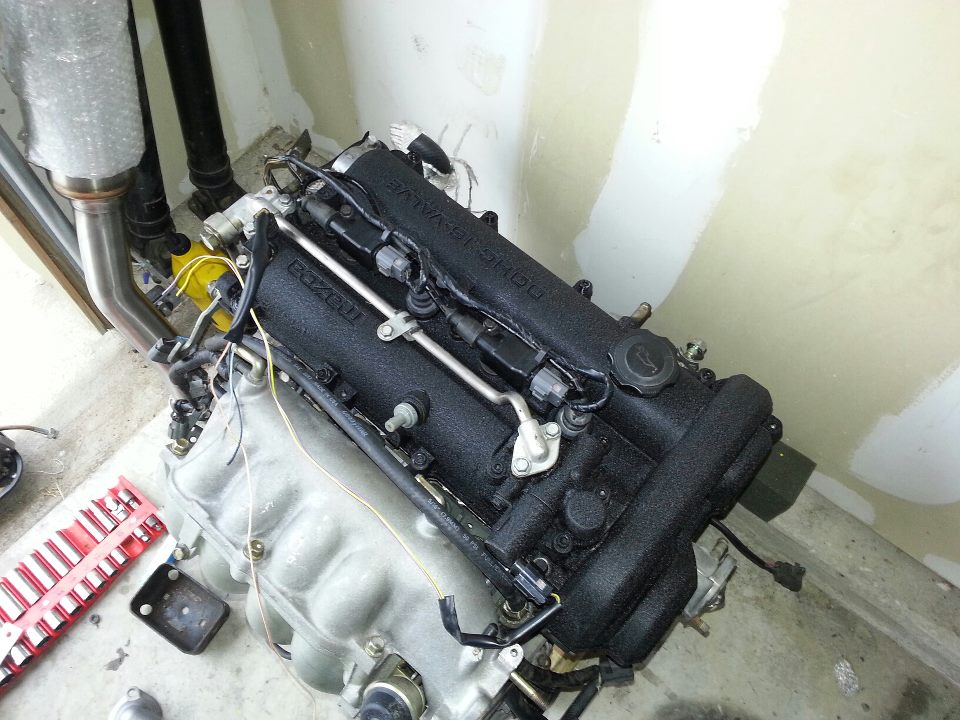
Engine is ready to come out, wire splice key is written, and I'm tired. I still need to get the header EGR bung welded closed, get a new O2 sensor bung, hopefully this throw out bearing I got is the right one, need heater hoses, then the engine goes in. I'm using an old OEM clutch so hopefully it works for <= 150whp. It looked good with no heat marks so hopefully it works out.
Reply
0
0
Thread Starter
Joined: Jun 2006
Posts: 29,085
Total Cats: 375
From: Republic of Dallas
Here is my wiring cheat sheet for 1994 chassis using a 2001 engine:
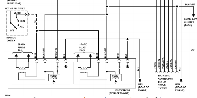
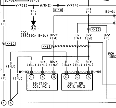
Coils:
1994----------------------------VVT harness
#1
black----------------------------black
blue----------------------------black/white
brown/yellow----------------------------brown/white (check for the third, signal wire and connect here)
#2
black----------------------------black
blue ----------------------------black/white
brown*--------------------black/yellow (check for the third, signal wire and connect here)
*The wiring on my 1994 was inconstent from wire diagrams. One brown wire was brown/white, the other was black/yellow. The coils wiring that came with my VVT engine looked to have coil #1 and #2 swapped. Connecting the signal wires requires thought and a multi-meter. I believe BR/W is #1, B/Y is #2. It's hard to guess because each have features of the one listed in the diagram.
CMP:
1994----------------------------VVT harness
yellow/blue--------------------gray/blue
white----------------------------no
red/white*-----------------------red/white
black/green*--------------------black/blue
CKP:
1994----------------------------VVT harness
white---------------------------gray/blue (signal)
red/white*--------------------red/white (power)
black/green*------------------black/blue (gnd)
Basically black wires are grounds, the other is signal, also inconsistent from wire diagrams on my pig-tail
*="Y" splice
If someone wants to proof that, great.
Last edited by hustler; Feb 14, 2013 at 03:12 PM.
Reply
0
0
Thread Starter
Joined: Jun 2006
Posts: 29,085
Total Cats: 375
From: Republic of Dallas
If all this is right I'll put this cheat sheet on the first post and maybe I'll for the first time have something to contribute to "useful saved posts".
Reply
0
0
Thread Starter
Joined: Jun 2006
Posts: 29,085
Total Cats: 375
From: Republic of Dallas
Dear Reverant,
Will I need to adjust the tach-out since I'm going to run the 99+ timing wheel settings? Does the NB Miata use a two-pulse/trigger set-up for the tach?
(I assume this will also be a problem on my 12-1 set-up for the green car)
Will I need to adjust the tach-out since I'm going to run the 99+ timing wheel settings? Does the NB Miata use a two-pulse/trigger set-up for the tach?
(I assume this will also be a problem on my 12-1 set-up for the green car)
Reply
0
0

So I am guessing the cam and crank pigtails I sent out made it to you this time?
Reply
0
0
Thread Starter
Joined: Jun 2006
Posts: 29,085
Total Cats: 375
From: Republic of Dallas
Not yet. I found a CMP piggy but still need one for my track car, if I go with NC sensors, which may be worth the $200 I have to pay for a cam wheel after all this. I'm kind of tired. I'll let you know when it arrives.
Reply
0
0


