
Build Thread (FE3, RX7 TII, EFR 6258, MS3)


Yes CJ7. I removed the capture portion of the mount as it made contact with the sub frame. I suspect i'm getting excess vibrations through it. If not, they are a whopping 7$ to replace.
Reply
 0
0

0


Just FYI.
This is the game plan.
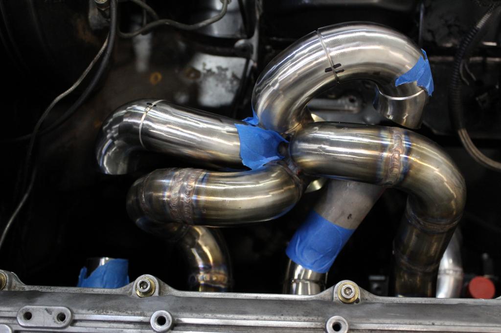
Going to tack up these next 2 runners, Pull them off at the collector and the port, weld them up, then cross my fingers and hope that it doesn't warp out of shape too much, then weld in the full section last.
Any pro tips? Maybe leave the ends tacked and weld as much as i can, then cut the ends loose and finish? This is literally the 2nd exhaust manifold I've ever made. Going for something a little better than my mig'd POS i made the first time.
Reply
1
1

Once the whole thing is tacked up cut the runner off the collector and the head, fully weld them, then weld back to the collector. Make the weld connection to the manifold last to avoid most of the warping. And bolt the fland down good when you weld to the flange. And when you weld the flange, do like 1/2" bead on each runner and move down the line, once you do all 4 then start the next bead 180 out of the first one. Thats how I did mine, and I only bolted mine to a stock exhaust flange, no warpage at all. Take your time, keep the heating even, give it time too cool down every few passes and it wont warp.
Reply
0
0

What I do:
1" thick threaded heat sync for head flange when you do those welds (last welds for me)
For runner welds, break each runner in half and weld separately. when it warps, you have 3 spots now to make it fit instead of 2. (collector and head)
Place the runner halfs where you want them and then tack the **** out of it on the runner and runner to collector. do a nice tack where you can easily cut them off on the head flange. weld the runner and runner to collector now.
Cut the tacks off the head flange, deck all 4 runners where they meet the head flange on your large belt sander so that they fit nice and flat on the flange. bevel what you just decked so you get good penetration, tack in place on head flange to confirm alignment before you weld it all up and your good.
Deck the head flange after its naturally cooled (don't quench it) on the nice heat sync you have made. it will still warp a little bit, especially if your using stainless flanges.
Side note: whats up with the fore/aft angle of the turbo flange? You ideally want the turbo to sit flat that way.
Reply
0
0
Reply
0
0
I do.
I never want a customer to have an issue while I full well know that it could be an issue.
I was asking about it, I'm not being critical of his work, but it is a best practice to have it mount level. There are some setups that don't do this (k series Hondas for example) and I have no experience with the angles but I follow manufacturers recommendations to a t.
Reply
0
0

Elite Member
Joined: Apr 2010
Posts: 2,826
Total Cats: 66
From: Newcastle, Australia
Why does the few degrees hurt it?
Because of oil or something?
Acceleration and braking is a hell of a lot worse than 10 degrees. Is it a long term balance issue, bearing wearing unevenly or something?
Dann
Because of oil or something?
Acceleration and braking is a hell of a lot worse than 10 degrees. Is it a long term balance issue, bearing wearing unevenly or something?
Dann
Reply
0
0
oil backs up in the center section on the side that's lower. its more of a long term reliability thing at a low angle. a high angle like some pro-stock type drag racers or the 30 degrees a Honda k series manifold would sit the turbo at would cause an issue with oil control before what I would consider "long term"
Reply
0
0
BW lists the angle range to stay within, I'd just follow it.
Some turbos are setup for angle though, like the older subaru WRC turbos, they were mounted at like greater than a 45.
Some turbos are setup for angle though, like the older subaru WRC turbos, they were mounted at like greater than a 45.
Reply
0
0
Should have seen the customer that came in our shop the other day with a custom turbo kit on his C5 Vette. The Turbo was mounted such that the turbine was on a vertical axis, no oil or water lines plumbed, open dump out the turbine housing and best part, the turbo drive pipe was only Tee'd into the existing exhaust system. We facepalmed pretty hard that day.
Thanks for all the advice guys. The slight angle is for wastegate actuator-chassis clearance, better intake and downpipe routing, slightly better hood clearance. I'm confident in my bearing housing cooling solution so i don't expect oil to coke up.
Thanks for all the advice guys. The slight angle is for wastegate actuator-chassis clearance, better intake and downpipe routing, slightly better hood clearance. I'm confident in my bearing housing cooling solution so i don't expect oil to coke up.
Last edited by yank; Jul 10, 2014 at 02:01 PM.
Reply
0
0


