
93' Miata stolen and flipped build thread


Personally, when I "prime" a turbo, I physically hold the impeller and have someone start the car. Sounds scary but the exhaust pressure at idle is nearly nothing and you can barely feel it attempting to spin. I give it about 15-20 seconds before I let go.
If you're truly paranoid, you can do this, but have the drain disconnected into a bucket to visually verify flow.
If you're truly paranoid, you can do this, but have the drain disconnected into a bucket to visually verify flow.
Reply
 0
0

0

Elite Member
Joined: Oct 2013
Posts: 2,764
Total Cats: 951
From: Cedar City, UT
Well this next project should be a good intro into becoming good at soldering....
I pulled apart the power unit to the COP harness since I wanted to double check the connections were solid. I'd hate to do all this rewiring and then have a dead COP harness and not know why.
Glad I did, the very left wire had broken the pin in half and the other pins were on the verge. Who knows what was my fault for breaking loose the wires from their bonds of sealant...jesus that was a lesson in irritation.
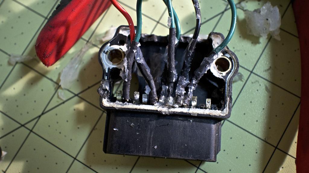
So after I found out the pin had broke I was temporarily of the mindset "I'm screwed" until I can order a new one. Luckily the P.O. had a couple extras in the boxes of goodies I got with the car.
So after very very carefully separating the metal backing off the plastic housing, I was like, "sweet! Lets start soldering!" Wrong! Holy unrighteous spooge of stickiness. Whatever the electrical adhesive or grease they used is the stickiest crap I've ever come into contact with. After going at it with some tweezers I finally broke out the electrical cleaner...nada, brake cleaner...nada...goo off...jackpot. Nice clean metal to solder to.
Instead of cutting off the back of the plastic, I'm going to drill an individual hole for each wire to go through. Then add a little sealant around the holes. Then I'm going to pry off the electrical part of the metal and reattach it to have a nice sealed unit without spooging 6oz's of sealant all over the wires, making it hell to work on if I ever need to tear it apart again.
evidence of the slime of which would bring the apocalypse
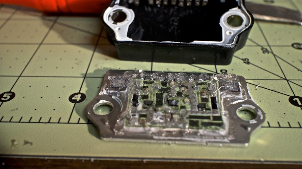
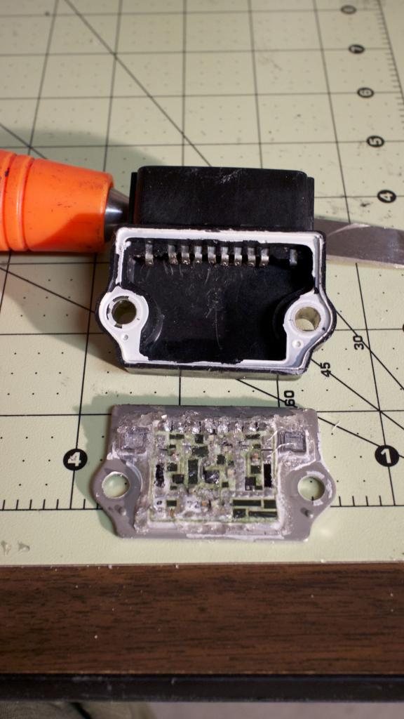
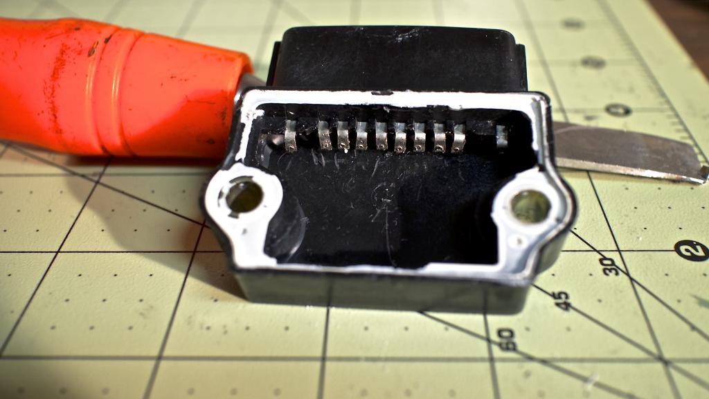
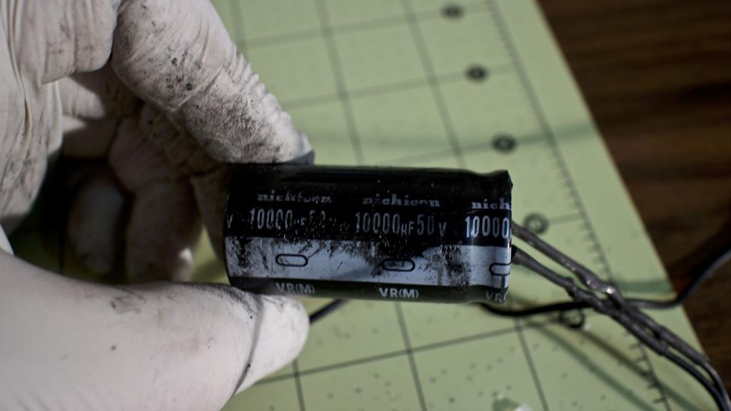
Is it worth replacing this diode?
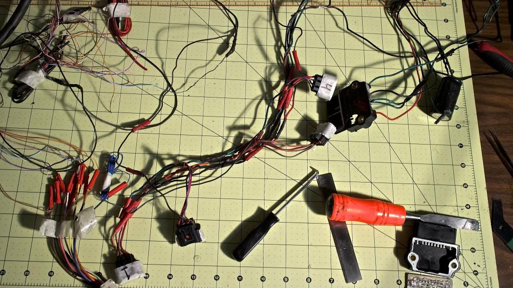
The mess of the COP harness I'm dealing with. I'm not going to replace the female connectors, rather, cut off the butt connectors and use the NASA style of soldering for a just-as-strong-as-crimping connection. If it works on the space shuttle, it should work on a miata. (ref. http://www.hq.nasa.gov/office/codeq/doctree/87394.pdf "19.6")
I know how you folks here hate soldering, so don't judge me. I am just trying to save some money here, I still need to budget to:
Paint the hard top
Get an alignment
Register the car
Pay sales tax on the purchase of the CO car
Insure it
and keep money in reserve for some other unforeseen problem I may or may not have after the alignment. Who knows if there actually is damage to any subframe/suspension part after the car caught the embankment and rolled over.
I pulled apart the power unit to the COP harness since I wanted to double check the connections were solid. I'd hate to do all this rewiring and then have a dead COP harness and not know why.
Glad I did, the very left wire had broken the pin in half and the other pins were on the verge. Who knows what was my fault for breaking loose the wires from their bonds of sealant...jesus that was a lesson in irritation.

So after I found out the pin had broke I was temporarily of the mindset "I'm screwed" until I can order a new one. Luckily the P.O. had a couple extras in the boxes of goodies I got with the car.
So after very very carefully separating the metal backing off the plastic housing, I was like, "sweet! Lets start soldering!" Wrong! Holy unrighteous spooge of stickiness. Whatever the electrical adhesive or grease they used is the stickiest crap I've ever come into contact with. After going at it with some tweezers I finally broke out the electrical cleaner...nada, brake cleaner...nada...goo off...jackpot. Nice clean metal to solder to.
Instead of cutting off the back of the plastic, I'm going to drill an individual hole for each wire to go through. Then add a little sealant around the holes. Then I'm going to pry off the electrical part of the metal and reattach it to have a nice sealed unit without spooging 6oz's of sealant all over the wires, making it hell to work on if I ever need to tear it apart again.


evidence of the slime of which would bring the apocalypse

Is it worth replacing this diode?

The mess of the COP harness I'm dealing with. I'm not going to replace the female connectors, rather, cut off the butt connectors and use the NASA style of soldering for a just-as-strong-as-crimping connection. If it works on the space shuttle, it should work on a miata. (ref. http://www.hq.nasa.gov/office/codeq/doctree/87394.pdf "19.6")

I know how you folks here hate soldering, so don't judge me. I am just trying to save some money here, I still need to budget to:
Paint the hard top
Get an alignment
Register the car
Pay sales tax on the purchase of the CO car
Insure it
and keep money in reserve for some other unforeseen problem I may or may not have after the alignment. Who knows if there actually is damage to any subframe/suspension part after the car caught the embankment and rolled over.
Last edited by Jeffbucc; Mar 8, 2014 at 06:51 AM.
Reply
0
0


Reply
1
1
Elite Member
Joined: Oct 2013
Posts: 2,764
Total Cats: 951
From: Cedar City, UT
Reply
0
0
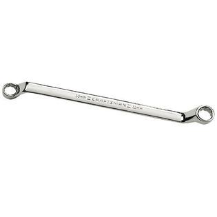
^ I've used a slim profile 1/4" ratchet and 10mm socket with great success. You have to get the bolt going with just the socket on the head at first, but yeah... no problems tightening that guy.
I use a Craftsman slim 1/4" ratchet.
I use a Craftsman slim 1/4" ratchet.
Reply
0
0

I have no issues using a 10mm angled box wrench either, however my dash doesn't sit all the way back, so I need to push the dash forward as I try to tighten it. I thought everyone struggled with it. Apparently not. My main point was that there is an airbag sensor back there...
Reply
0
0


Reply
0
0
Elite Member
Joined: Oct 2013
Posts: 2,764
Total Cats: 951
From: Cedar City, UT


Not much progress done, I needed a mental break from the car. I did get 1/2 the COP harness done though.
After reading up and doing some practice on some scrap wire I think my solder penetration isn't too shabby. Nice and strong. I know you guys who are actually good at this are laughing at me right now, but it'll do for me. Better than a shitload of butt connectors.

Heatshrinked

Ready to put in some 1/2" heatshrink

Struggled with pulling it through that long of a length of heatshrink until I taped the wires to a 4' length of bicycle brake cable and pulled it through.
It isn't very pretty but I plan on buying some nice looking wrap to give it a good professional look. Once the ground wires are all done I'm going to wrap all 4 wire bundles together for one nice thick rope.
Using Thasac's Harness for a little inspiration on this one.


criticism is welcome, I fully accept my flaws at this whole "wiring" thing. I don't think my brain is wired(
 ) for it.
Reply
3
3
Oh, are you running sequential? Very nice...
Consider this stuff:
X-Treme� Tape Silicone Rubber Self Fusing Tape
Good to 600psi, dielectric to 400 volts per mil, and good for up to 500*f. Little bit goes a long way, and it's like really thick electrical tape that fuses to itself.
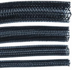
Although I like the webbed look better myself:
Consider this stuff:
X-Treme� Tape Silicone Rubber Self Fusing Tape
Good to 600psi, dielectric to 400 volts per mil, and good for up to 500*f. Little bit goes a long way, and it's like really thick electrical tape that fuses to itself.
Although I like the webbed look better myself:
Reply
0
0

Jeff, awesome work as always! About the soldering, do you have a flux pen?
I used to think I couldn't solder, then I learned about this:

A flux pen is truly MAGICAL. Words cannot describe how much better my work comes out now. I also stopped using garbage leadless Rat Shack solder and switched over to MG Chemicals Sn63/Pb37 solder. They sell these at Fry's Electronics if you have one nearby.
A flux pen is truly MAGICAL. Words cannot describe how much better my work comes out now. I also stopped using garbage leadless Rat Shack solder and switched over to MG Chemicals Sn63/Pb37 solder. They sell these at Fry's Electronics if you have one nearby.
Reply
0
0
Elite Member
Joined: Oct 2013
Posts: 2,764
Total Cats: 951
From: Cedar City, UT
I'm having a really hard time finding wiring information on sequential setups. Some say run all 4 sequential and others state only 2&4 are necessary.
The car does have MS3X. Does anyone have a link as to the proper way to do sequential?
I love the webbing look. Can you buy that local or do you need to order that online?
No flux pen. I think some of my soldering flaws are from being impatient and not allowing the soldering iron to heat up the wires to the point that the wires melt the solder rather then the iron itself.
Reply
0
0
Elite Member
Joined: Oct 2013
Posts: 2,764
Total Cats: 951
From: Cedar City, UT

Got the other 2 wires done, just need to solder them into the power source, the capacitor, and the MS3 connector for the sequential firing of 2&4.

Reply
1
1

Firing order is 1342, and the injectors are paired 1&2 and 3&4, so the OEM wiring would be cut from 1&3 or 2&4 and then wired into the additional injector drivers on your ECU.
Hope that makes sense.
You can't have 2 & 4 running sequentially and 1 & 3 not**.
** well you could, but it'd be a ******* weird setup to do.
Reply
0
0
Elite Member
Joined: Oct 2013
Posts: 2,764
Total Cats: 951
From: Cedar City, UT
Full sequential is each injector is individually controlled, rather than paired with other injectors, (known as batch injection). 1.6 owners add 2 extra wires as normally the injectors are paired up. the extra two wires allows each injector to be controlled individually. These are used in conjunction with the 2 wires already connected up to the injectors.
Firing order is 1342, and the injectors are paired 1&2 and 3&4, so the OEM wiring would be cut from 1&3 or 2&4 and then wired into the additional injector drivers on your ECU.
Hope that makes sense.
You can't have 2 & 4 running sequentially and 1 & 3 not**.
** well you could, but it'd be a ******* weird setup to do.
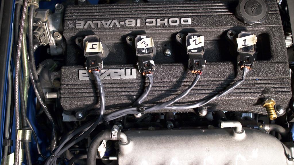
The next info is assuming pin 1 starts on the left on the COP.

See that is why I'm confused. COP 2&4 are wired for sequential. Both go to a separate pin on a connector. Then COP #3/pin-3 is wired to OC1 on the power unit. COP #1/Pin-3 is wired to IB2 on the power unit.
(This connector for 2&4)

The other pins all go to these locations on the power unit.
COP 1-4/Pin-1 goes to VB
COP 1-4/pin-2 goes to TAC and IGT
COP 1-4/pin-4 goes to GND

Last edited by Jeffbucc; Mar 10, 2014 at 05:19 AM.
Reply
0
0
Sorry missed you were talking about COPS not injectors.
Principal is identical though, just the pairings are different. 1&4 and 2&3 are paired as stock.
Sounds like the wiring just retains the OEM run for 2 of the coils, then adds 2 extra. It's only the signal lines that have to be added, the rest can all be paired up (12v etc). Tach you only want 2 of the 4 to reach the cluster, or the tacho will read 2x too fast.
Reply
0
0
Elite Member
Joined: Oct 2013
Posts: 2,764
Total Cats: 951
From: Cedar City, UT
Sorry missed you were talking about COPS not injectors.
Principal is identical though, just the pairings are different. 1&4 and 2&3 are paired as stock.
Sounds like the wiring just retains the OEM run for 2 of the coils, then adds 2 extra. It's only the signal lines that have to be added, the rest can all be paired up (12v etc). Tach you only want 2 of the 4 to reach the cluster, or the tacho will read 2x too fast.
Principal is identical though, just the pairings are different. 1&4 and 2&3 are paired as stock.
Sounds like the wiring just retains the OEM run for 2 of the coils, then adds 2 extra. It's only the signal lines that have to be added, the rest can all be paired up (12v etc). Tach you only want 2 of the 4 to reach the cluster, or the tacho will read 2x too fast.
Good news is I've gotten better at soldering, not bad if I say so myself...

And the power unit wiring(this may be wrong but I copied the original wiring exactly(and the car ran perfect with said wiring)

Reply
0
0
Elite Member
Joined: Oct 2013
Posts: 2,764
Total Cats: 951
From: Cedar City, UT
OK, glad most of the work is done. Only things left are to wire 2/4 to the MS3 connector and some superficial pretty wrap.
Capacitor makes it look bulky but everything is nice and tidy. Ground was a butt connector with a plastic insulator on it; but I didn't like how secure it was so I cut off the plastic, crushed the butt connector, soldered the wires to the ground, and put some heat shrink around it. Much better.
I'm happy with how it turned out for my first time doing some slightly "real" wiring.
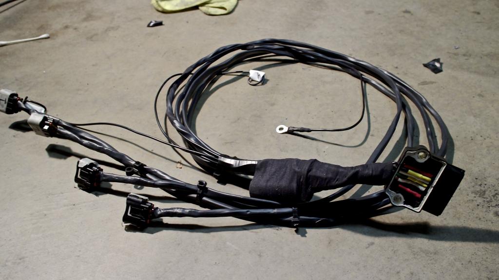
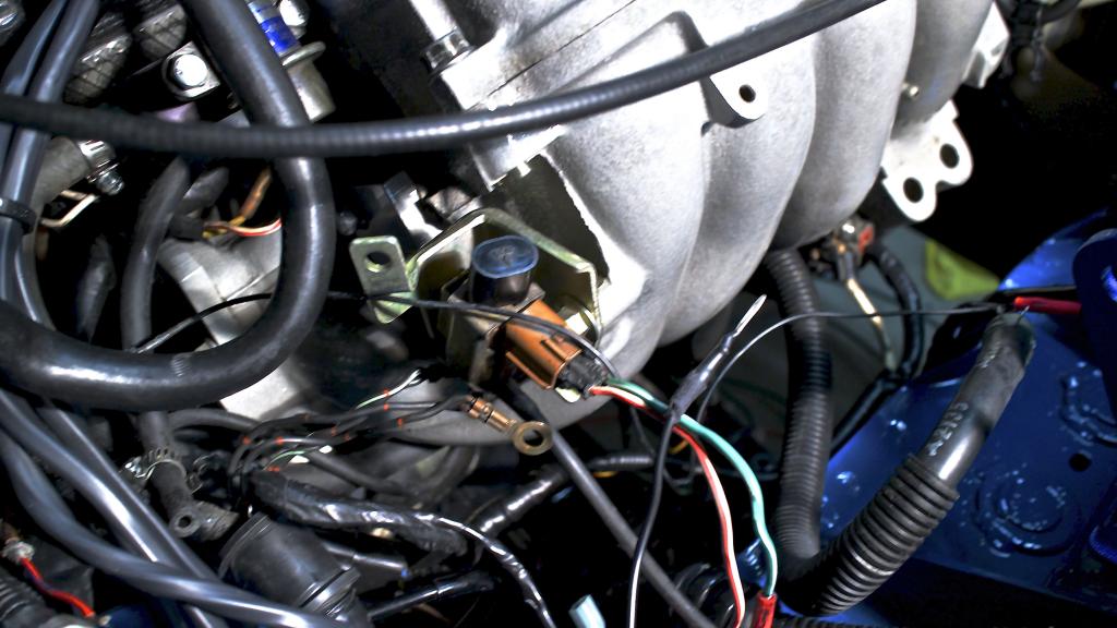
Rough mock up of it on the VC.
The thick part of the cable hides nicely under the fender.
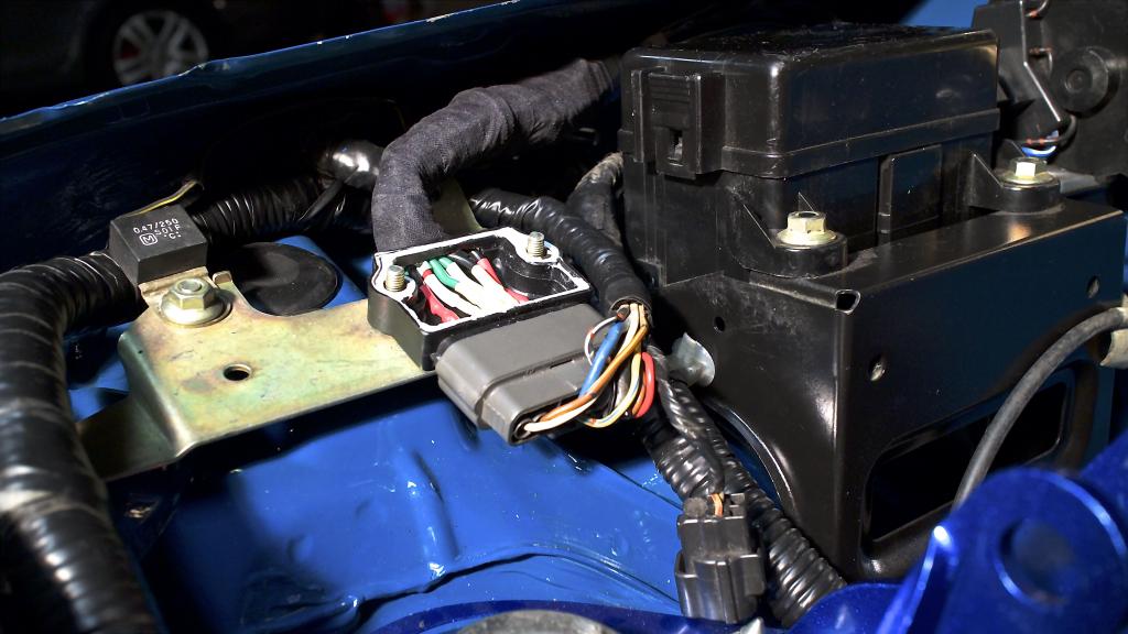
I'm guessing this is the adjustable fuel regulator? Has a bolt on the back of it that a ton of grounds bolt on to.
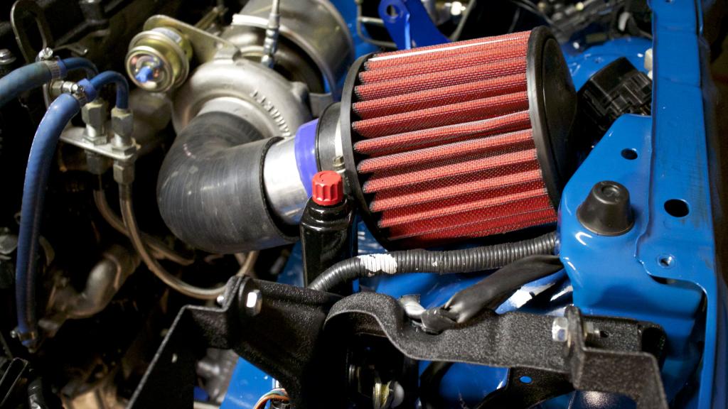
Some how massively screwed up when I order the air filter, way too big for the hood to close.
Capacitor makes it look bulky but everything is nice and tidy. Ground was a butt connector with a plastic insulator on it; but I didn't like how secure it was so I cut off the plastic, crushed the butt connector, soldered the wires to the ground, and put some heat shrink around it. Much better.
I'm happy with how it turned out for my first time doing some slightly "real" wiring.

Rough mock up of it on the VC.

The thick part of the cable hides nicely under the fender.

I'm guessing this is the adjustable fuel regulator? Has a bolt on the back of it that a ton of grounds bolt on to.

Some how massively screwed up when I order the air filter, way too big for the hood to close.


Reply
1
1


