
COP Thread


Junior Member
Joined: May 2010
Posts: 50
Total Cats: 7
Sorry if this has been resolved already, I'm at work and can only do so much searching.
I wired and installed my COP setup and got it running on my Braineack built DIYPNP for my 94. It seems to work fine so far except when I hit 4k rpm, my dash tach shoots to redline while my tunerstudio tach remains normal.
Any ideas what could be causing this or what I might need to change on my megasquirt?
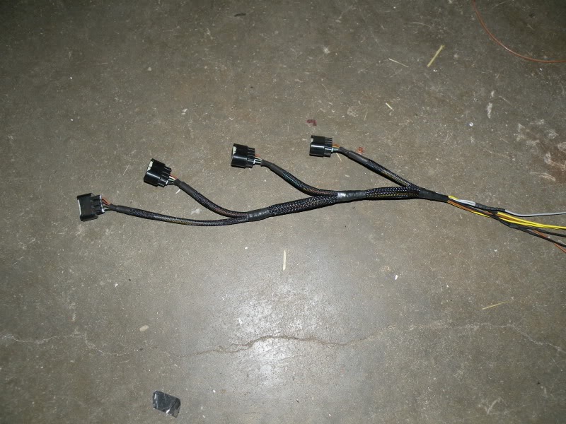
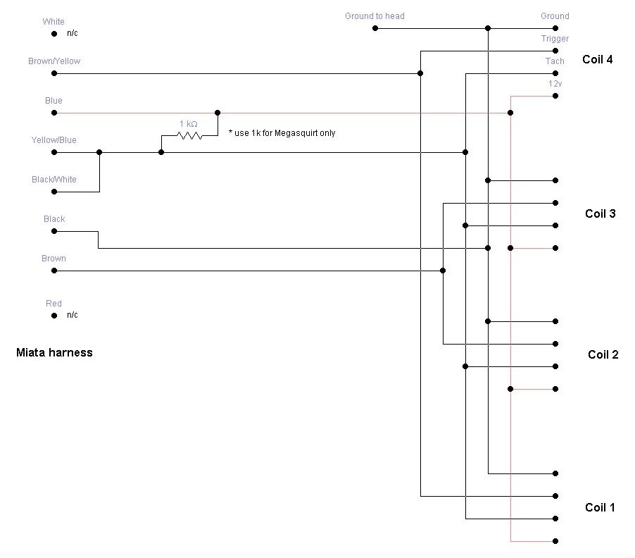
I wired all 4 coils to the blue on one original connector, all 4 tach and grounds as well to their respective wire on 1 connector as well as a ground wire to the back of the valve cover. And the triggers to their respective wires on the connectors.
Should I have separated the tach wiring? I just ran 1 wire up to the first coil and then soldered branches into that wire as it passed by the other coils. The other shared wires (GND and +12) are done the same way.
I wired and installed my COP setup and got it running on my Braineack built DIYPNP for my 94. It seems to work fine so far except when I hit 4k rpm, my dash tach shoots to redline while my tunerstudio tach remains normal.
Any ideas what could be causing this or what I might need to change on my megasquirt?
I wired all 4 coils to the blue on one original connector, all 4 tach and grounds as well to their respective wire on 1 connector as well as a ground wire to the back of the valve cover. And the triggers to their respective wires on the connectors.
Should I have separated the tach wiring? I just ran 1 wire up to the first coil and then soldered branches into that wire as it passed by the other coils. The other shared wires (GND and +12) are done the same way.
Reply
 0
0

0


Junior Member
Joined: May 2010
Posts: 50
Total Cats: 7
+12 runs from coil 1 to blue on the 1/4 connector with branches soldered in for 2, 3 and 4.
GND runs from coil 1 to black on the 1/4 connector and a lug on the valve cover with branches soldered in for 2, 3 and 4.
Tach runs from coil 1 to black/white on the 1/4 connector with branches soldered in for 2, 3 and 4.
Trigger for 1/4 runs from coil 1 to brown/yellow with a branch soldered in for 4.
Trigger for 2/3 runs from coil 2 to brown with a branch soldered in for 3.
I have a 10k microfarad cap between +12 and GND.
I tried a 1k ohm resistor from +12 to -IGN in the DIAG box with no effect. I'll check later though whether its actually contacting anything. Maybe theres some crud on the contacts or something.
Reply
0
0

so i got a AEM twin fire CDI ignition system for xmas, i plan on running a set of the AEM pencil coils with this set up, i dont have access to my car at the moment, can someone tell me how long is the plug boot? theres 2 options for the pencil coils 5.72in or 6.65. which is closest?
Reply
0
0
http://cgi.ebay.com/ebaymotors/AEM-C...Q5fAccessories
heres a picture of the kit btw, i just got the CDI box for now and will get the coils when i get extra money.
heres a picture of the kit btw, i just got the CDI box for now and will get the coils when i get extra money.
Reply
0
0

So, I see a lot of peoples harnesses for the 1.6 cars what capacitors are you guys running? 10000uF or I have seen two 4700uF in parallel? Any ideas as to what they are impedance-wise, low, high, general electronics? I'm looking on mouser and have found some 10000uF caps but they are freaking huge 21mm diam 31mm L. Any help would be good. Is this schematic correct for MSPNP? Is that a 1K ohm resistor? Where's the capacitor in this diagram?
Last edited by JEMERY; Feb 10, 2011 at 04:35 PM.
Reply
0
0

The schematic shows a 1K ohm resistor (1000 ohm )
The caps can be two 4700uf in parallel, They need to be polarized electrolytic rated at something over 12v. I think mine were 35vdc. They are not shown.
The ones you saw may be rated for a higher voltage or something else.
The caps can be two 4700uf in parallel, They need to be polarized electrolytic rated at something over 12v. I think mine were 35vdc. They are not shown.
The ones you saw may be rated for a higher voltage or something else.
Reply
0
0

So, I see a lot of peoples harnesses for the 1.6 cars what capacitors are you guys running? 10000uF or I have seen two 4700uF in parallel? Any ideas as to what they are impedance-wise, low, high, general electronics? I'm looking on mouser and have found some 10000uF caps but they are freaking huge 21mm diam 31mm L. Any help would be good. Is this schematic correct for MSPNP? Is that a 1K ohm resistor? Where's the capacitor in this diagram?
Reply
0
0

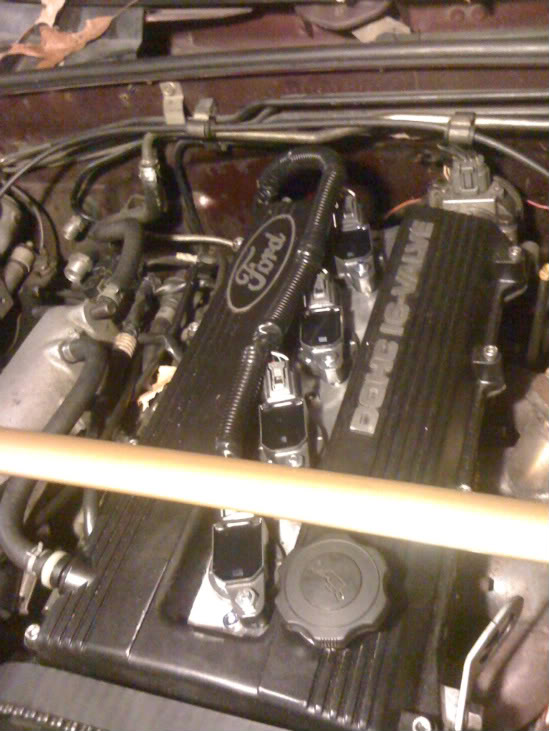
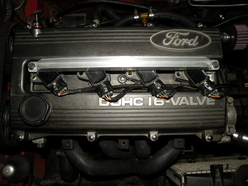
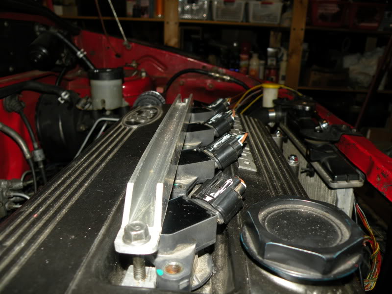
ok, so i just made the Cop setup pictured above for my 93 miata 1.6. when i installed it the car would start and run for a second and then shut off. my tach never moves so that would indicate to me there is a problem with the tach signal. however if i leave the cop set up wired in and leave the cop's on the spark plugs while i have the stock coil pluged into the cars harness the car runs like a champ and my tach works fine. ive checked my wiring a few times and it all appears correct. and i am running a stock ecm. any ideas?????
Reply
0
0

Elite Member
Joined: Mar 2006
Posts: 1,574
Total Cats: 106
From: Schwarzenberg, Germany
I just ordered myselb the 10000 uF caps to fit in my existing Cop harness. What I did forget is, that as an NB user I got 2 line with ground and +12V separated always for two cylinders.
Can I use two of the 10000uF caps - one in each pair of lines or should they be more like 5000uF each...?
Can I use two of the 10000uF caps - one in each pair of lines or should they be more like 5000uF each...?
Reply
0
0

I just ordered myselb the 10000 uF caps to fit in my existing Cop harness. What I did forget is, that as an NB user I got 2 line with ground and +12V separated always for two cylinders.
Can I use two of the 10000uF caps - one in each pair of lines or should they be more like 5000uF each...?
Can I use two of the 10000uF caps - one in each pair of lines or should they be more like 5000uF each...?
I just built mine - not tested or installed - using this schematic http://miataturbo.wikidot.com/cop for 95.5+. It shows common ground and +12v. I'm going to be grounding at the front of the intake manifold and pulling +12v (unswitched) through a relay off the under hood fuse panel. The control for the relay is the +12v that normally powers the stock coils.
So, just wondering Zaphod, where are your separated ground and +12v connected? And, did I miss something before I plug this in and fry it?
Reply
0
0


