
COP Thread


Junior Member
Joined: Oct 2009
Posts: 330
Total Cats: -3
From: Anderson, SC
I've decided to tackle this mess and get few things that confuse me straightened out. Brain were u trolling with the 5 volt?
My one question is theres 2 harnesses on the stock 99-00 coils. Also what do u do for the 2 harnesses? Do you have to cut them out from the stock coils or is there an alternative?
The wiring harness in the discussion cops thread shows 1 harness, sup with that?
The next thing is some people say use a capacitor between the gnd and the 12volt, others say not to. Do i need it for my 99 car? How about the resistor? I have no tach wire so i take it i dont need it either?
Reply
 0
0

0

I got a dead 99/00 coilpack and cut off the connectors to make a plug-and-play setup, but I discovered it was VERY difficult to remove the insulation filling in the connector and solder to the wire stubs. I purchased an extra PAIR (just in case) of coil/sensor/injector harnesses for a 99/00 here in the classifieds or from PartsGroup and built a hardwired harness. MUCH cleaner, though it is significantly harder to remove. I tried to use a 6 wire weatherpack but my crimps have proven unreliable.
I also added an additional ground that goes to a bolt on the back of the head. Because **** you, that's why.
Correct.
Last edited by EO2K; Jan 4, 2013 at 04:52 PM.
Reply
0
0
On the NBas i unplugged the cam sensor and the tach went to 0. Somehow i'm not subscribed to this thread so i didnt see the replys.
Reply
-1
-1


For those running COPs on their 1.6, did you add a second ground to the head?
I noticed there are 2 'lazzer' diagrams floating around the internet and one utilizes the OEM harness ground wire and the other adds an additional ground at the head.
I was going to opt of of the second ground since it seems like over kill and it's one more piece of cooper spagetti cluttering up my bay.
-Zach
Reply
0
0


Newb
Joined: Apr 2013
Posts: 2
Total Cats: 0
From: Victoria BC
2 weeks? My COPs took 6 months plus a couple track days worth of stock ECU abuse before I finally damaged one. Maybe the ones I'm using are a bit more robust?
IDK how IL treats inspections, but would COPs even pass a visual? If you are already swapping injectors and crap, you might as well just suck it up and install the stock coil. Its not that much more work once you are already in there. I actually have 2 injector/ignition harness for exactly this reason.
IDK how IL treats inspections, but would COPs even pass a visual? If you are already swapping injectors and crap, you might as well just suck it up and install the stock coil. Its not that much more work once you are already in there. I actually have 2 injector/ignition harness for exactly this reason.
Reply
0
0

Hi there
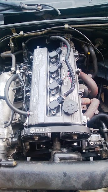
This thread made the COP install super easy.
just got it installed yesterday and put on my escort valve cover i grabbed at the jyard for cheaps. (lol they also had a racingbeat style bar I got for 5 bucks!)
I have yet to paint the VC but heres how she looks! running like a baws.
This thread made the COP install super easy.
just got it installed yesterday and put on my escort valve cover i grabbed at the jyard for cheaps. (lol they also had a racingbeat style bar I got for 5 bucks!)
I have yet to paint the VC but heres how she looks! running like a baws.
Reply
0
0

Okay so I got my cops made but my tach isn't working. I believe this is because I didn't use a capacitor and resistor. Where am I suppose to tap it into? Somewhere in the harness? I'm not too sure if this is causing my leaning issue. Right now it's grounded to the head, and so is my wideband. Would that cause any interference? Will I need to add an extra ground?
Last edited by AdoboMiata; Aug 4, 2013 at 07:47 PM.
Reply
0
0

Okay so I got my cops made but my tach isn't working. I believe this is because I didn't use a capacitor and resistor. Where am I suppose to tap it into? Somewhere in the harness? I'm not too sure if this is causing my leaning issue. Right now it's grounded to the head, and so is my wideband. Would that cause any interference? Will I need to add an extra ground?
Reply
0
0
Mine is a 92. 1.6. I'm going to have to figure out this leaning issue
Reply
0
0
Thread Starter

Joined: May 2005
Posts: 80,588
Total Cats: 4,371
From: Chantilly, VA
Okay so I got my cops made but my tach isn't working. I believe this is because I didn't use a capacitor and resistor. Where am I suppose to tap it into? Somewhere in the harness? I'm not too sure if this is causing my leaning issue. Right now it's grounded to the head, and so is my wideband. Would that cause any interference? Will I need to add an extra ground?
put a 1K resistor between IG- and B+ in your diagnostics box.
it's not the capacitor, it was the lack of resistor.
The Stock ECU provides a pull-up for the tach. This comes out 2I on teh Black/White wire.
When you build the harness, you need to connect the black/white to yellow/blue, which is the tach wire that goes out from the ignitor.
If you remove the stock ECU, you remove the pull up, so you need a 1K resistor from 12v to the yellow/blue wire. Luckily, this wire goes to the diagnostics box via Ig-.
Otherwise, you can make the appropriate connections in your ECU harness and send a 1K pull to 12v out through 2I.
Reply
0
0
put a 1K resistor between IG- and B+ in your diagnostics box.
it's not the capacitor, it was the lack of resistor.
The Stock ECU provides a pull-up for the tach. This comes out 2I on teh Black/White wire.
When you build the harness, you need to connect the black/white to yellow/blue, which is the tach wire that goes out from the ignitor.
If you remove the stock ECU, you remove the pull up, so you need a 1K resistor from 12v to the yellow/blue wire. Luckily, this wire goes to the diagnostics box via Ig-.
Otherwise, you can make the appropriate connections in your ECU harness and send a 1K pull to 12v out through 2I.
Reply
0
0
So I think I have found my leaning issue. While running the car, I removed the coil from cylinder 1 and noticed no difference in sound. I removed the coil on cylinder 2 and it was running rough. I removed the coil from cylinder 3 and it started running rough. I removed the coil from cylinder 4 and no difference in sound. I'm assuming it's only firing on 2 coils (cylinder 2 & 3). I tried using cylinder 2 coil on 1 and 4. Still no difference. Possibly bad wiring? I'm not running a capacitor or resistor and I have a mspnp.
Reply
0
0
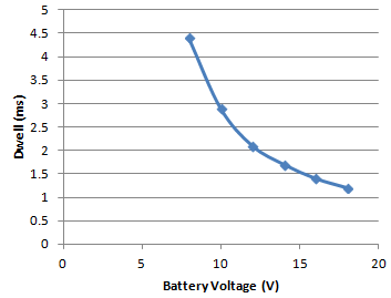
Aww fail. Trigger wire was soldered to the ground wire... Is there a possibility that I fried anything? I tried switching back to the stock coilpack.. I installed new wires, plugged in the harness, plugged in the ignitor, and changed the dwell settings (crank 8ms running 5ms).. Car is running like the ignitor is blown.. I swapped 3 other ignitors still runs the same.. Any ideas?
Reply
0
0

Reply
0
0
Once you unplug the coils, you will have 6 wires: 2 power, 2 ground, 2 triggers. The power and grounds actually go to the same sources so they are redundant. The diagram assumes you have joined the two power into one and the two ground into one, or simply ignored the second set of power and grounds in the second coil connector. Either way, you end up with 1 power, 1 ground, 2 triggers.
Reply
0
0


